But also from the purchase of a ready-made, full-fledged robot based on this board. For children primary school or preschool age such finished projects Arduino is even preferable, because The “unanimated” board looks a bit boring. This way suitable for those who electrical circuits not particularly attractive.
By purchasing a working robot model, i.e. actually a ready-made high-tech toy, you can awaken interest in independent design and the creation of robots. Having played enough of such a toy and understood how it works, you can begin to improve the model, take everything apart and start assembling new projects on Arduino, using the freed up board, drives and sensors. The openness of the Arduino platform allows from the same components make yourself new toys.
We offer a small overview of ready-made robots on the Arduino board.
Arduino machine controlled via Bluetooth
Car controlled via Bluetooth, costing just under $100. Supplied unassembled. In addition to the case, motor, wheels, lithium battery and charger, we get an Arduino UNO328 board, motor controller, Bluetooth adapter, remote control remote control And so on.
Video featuring this and another robot:
More detailed description toys and the opportunity to buy on the DealExtreme online store website.
Arduino Turtle Robot
Robot turtle assembly kit costing about $90. The only thing missing is the shell, everything else necessary for the life of this hero is included: Arduino Uno board, servos, sensors, tracking modules, IR receiver and remote control, battery.

The turtle can be bought on the DealExtreme website, a similar cheaper robot is on Aliexpress.
Arduino tracked vehicle controlled from a cell phone
Tracked vehicle, controlled via Bluetooth cell phone , costing $94. In addition to the track base, we get an Arduino Uno board and an expansion board, a Bluetooth board, a battery and a charger.
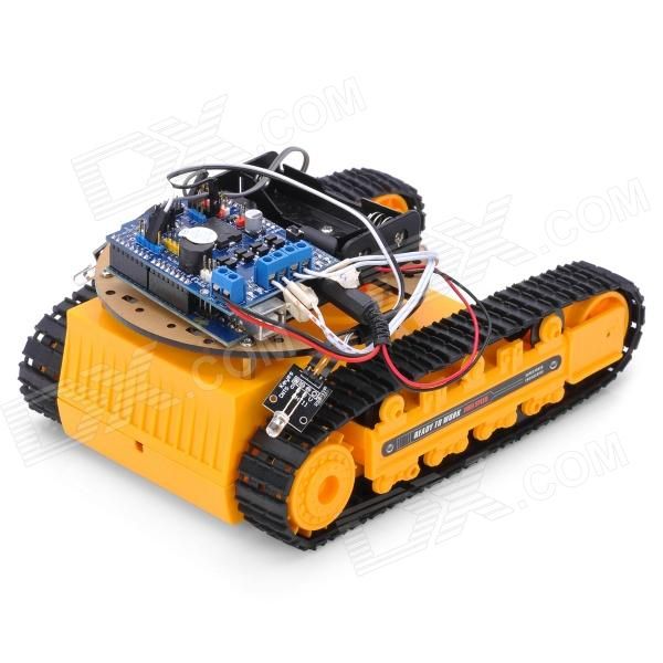
The tracked vehicle can also be purchased on the DealExtreme website, there is also a detailed description there. Maybe a more interesting iron one Arduino tank on Aliexpress.
Arduino car driving through mazes
Car driving through mazes, costing $83. In addition to motors, the Arduino Uno board and other necessary items, it contains tracking modules and obstacle avoidance modules.

Ready-made robot or frame for a robot
In addition to the option of using ready-made kits for creating Arduino robots discussed in the review, you can buy a separate frame (body) of the robot - it can be a platform on wheels or a caterpillar, a humanoid, a spider and other models. In this case, you will have to do the stuffing of the robot yourself. An overview of such cases is given in ours.
Where else can you buy ready-made robots?
In the review, we selected the cheapest and most interesting, in our opinion, ready-made Arduino robots from Chinese online stores. If you don’t have time to wait for a parcel from China - big choice ready-made robots in the online stores Amperka and DESSY. Low prices and fast delivery is offered by the online store ROBstore. List of recommended stores.
You might also be interested in our reviews of Arduino projects:

Arduino training
Don't know where to start learning Arduino? Think about what is closer to you - assembling your own simple models and their gradual complication or familiarization with more complex but ready-made solutions?
People start learning Arduino by creating simple robots. Today I will talk about the simplest robot on Arduino Uno, which, like a dog, will follow your hand or any other object that reflects infrared light. This robot will also amuse the kids. My 3-year-old nephew eagerly played with the robot :)
I'll start by listing the parts that will be needed during construction - Arduino UNO;
Infrared rangefinders;  -3-volt motors with gearboxes and wheels;
  - connectors for 3A batteries;
  -battery (if there are not enough batteries);
  -Relays to control the motors;
Well, and other materials that will be needed during the creation process.
First we make the base. I decided to make it out of wood. Wooden plank and sawed it in such a way that the motors fit perfectly in the slots 

Then I clamp the motors with a wooden strip, screwing this strip 
Next on the body I placed an arduino, a relay, a Bradboard, rangefinders, and a rotating chassis under the base 
Now we connect everything according to the diagram 
At the end, upload the following sketch to the Arduino:
Const int R = 13; //pins to which IR rangefinders are connected const int L = 12; int motorL = 9; //pins to which the relay is connected int motorR = 11; int buttonState = 0; void setup() ( pinMode(R,INPUT); pinMode(L,INPUT); pinMode(motorR,OUTPUT); pinMode(motorL,OUTPUT); ) void loop() ( ( buttonState = digitalRead(L); if (buttonState == HIGH)( digitalWrite(motorR,HIGH); ) else ( digitalWrite(motorR,LOW); ) ) (( buttonState = digitalRead(R); if (buttonState == HIGH)( digitalWrite(motorL,HIGH); ) else ( digitalWrite(motorL,LOW); ) ) ) )
The principle of operation is very simple. The left rangefinder is responsible for the right wheel, and the right one for the left 
To make it clearer, you can watch a video that shows the creation process and the operation of the robot
This robot is very simple and anyone can make it. It will help you understand the operating principles of modules such as relays and IR rangefinders and how best to use them.
I hope you liked this craft, remember that crafts are cool!
Hi all. This article is a short story about how do robot their hands. Why a story, you ask? This is due to the fact that for the manufacture of such crafts it is necessary to use a significant amount of knowledge, which is very difficult to present in one article. We'll walk through the build process, take a peek at the code, and ultimately bring a Silicon Valley creation to life. I advise you to watch the video to get an idea of what you should end up with.
Before moving on, please note the following: during manufacturing crafts a laser cutter was used. From laser cutter You can refuse if you have enough experience working with your hands. Precision is the key to completing the project successfully!

Step 1: How does it work?

The robot has 4 legs, with 3 servos on each of them, which allow it to move its limbs in 3 degrees of freedom. He moves with a “crawling gait.” It may be slow, but it is one of the smoothest.
First, you need to teach the robot to move forward, backward, left and right, then add an ultrasonic sensor, which will help detect obstacles/obstacles, and then a Bluetooth module, thanks to which control of the robot will reach a new level.
Step 2: Necessary Parts

Skeleton made of plexiglass 2 mm thick.
The electronic part of the homemade product will consist of:

- 12 servos;
- arduino nano (can be replaced with any other arduino board);

- Shield for controlling servos;
- power supply (in the project a 5V 4A power supply was used);

- ultrasonic sensor;
- hc 05 bluetooth module;
In order to make a shield you will need:

- circuit board (preferably with common lines (buses) of power and ground);
- inter-board pin connectors - 30 pcs;
- sockets per board – 36 pcs;

- wires.
Tools:
- Laser cutter (or skilled hands);
- Super glue;
- Hot melt adhesive.
Step 3: Skeleton

Let's use a graphics program to draw the components of the skeleton.
After this, at any affordable way cut out 30 parts of the future robot.
Step 4: Assembly

After cutting, remove the protective paper covering from the plexiglass.

Next we start assembling the legs. Fastening elements built into parts of the skeleton. All that remains to be done is to connect the parts together. The connection is quite tight, but for greater reliability you can apply a drop of superglue to the fastening elements.

Then you need to modify the servos (glue a screw opposite the servo shafts).

With this modification we will make the robot more stable. Only 8 servos need to be modified; the remaining 4 will be attached directly to the body.

We attach the legs to the connecting element (a curved part), and this, in turn, to the servo drive on the body.
Step 5: Making the Shield

Making the board is quite simple if you follow the photographs presented in the step.


Step 6: Electronics

Let's attach the servo drive pins to the arduino board. The conclusions should be connected to correct sequence, otherwise nothing will work!


Step 7: Programming

It's time to bring Frankenstein to life. First, let's load the legs_init program and make sure that the robot is in the position as in the picture. Next, let's load quattro_test to check if the robot responds to basic movements, such as moving forward, backward, left and right.

IMPORTANT: You need to add an additional library to the arduino IDE. The link to the library is provided below:
The robot must take 5 steps forward, 5 steps back, turn left 90 degrees, turn right 90 degrees. If Frankenstein does everything right, we're moving in the right direction.

P. S: Place the robot on the cup, like on a stand, so that you don’t have to put it at the starting point every time. As soon as the tests showed normal work robot, we can continue testing by placing it on the ground/floor.
Step 8: Inverse Kinematics

Inverse kinematics is what actually drives the robot (if you are not interested in the math side of this project and are in a hurry to finish the project, you can skip this step, but knowing what drives the robot will always be useful).

In simple words, inverse kinematics, or IR for short, is the “part” of trigonometric equations that determine the position of the sharp end of the leg, the angle of each servo, etc., which ultimately determine a couple of preliminary settings. For example, the length of each step of the robot or the height at which the body will be located during movement/rest. Using these predefined parameters, the system will extract the amount by which each servo should be moved in order to control the robot using the given commands.
A little about the robot. First of all, the project had to be as inexpensive as possible. The body was created without any calculations or balancing; the main requirement for the body was minimum dimensions. So let's start assembling this robot.
Parts List:
1. A set of body parts and paws made of 1.5 mm plexiglass.
2. Arduino Mega or Uno (Mega is used) - 1 pc.
3. Micro servo drive (TowerPro SG90 is used) - 8 pcs.
4. Ultrasonic rangefinder HC-SR04 - 1 pc.
5. Battery size 18560, 3.7V (TrustFire 2400 mAh is used) - 2 pcs.
6. Battery holder size 18560 (using a converted container - packaging) - 1 pc.
7. Stand for printed circuit board 25 mm. (such stands are used) - 4 pcs.
8. Part of the breadboard.
9. Jumper wires.
10. Screw DIN 7985 M2, 8 mm. - 18 pcs.
11. Nut DIN 934 M2 - 18 pcs.
Assembly of the Z-RoboDog robot:
1. The robot body is made of transparent plexiglass with a thickness of 1.5 mm. All parts are laser cut according to a drawing made in CorelDraw:
2. Glue the body second glue. The strength of the glued body will be quite sufficient. When assembling, take into account the position of the holes on the bottom cover (look at the photo), or better yet, attach the board and make sure that everything matches. Attach the side walls so that the holes for the wires are closer to back wall. The wider hole on the back wall is for a USB cable, please take this into account when assembling.


3. Mark and drill holes (2 mm drill bit). Secure the servos to the housing using bolts and nuts (items 10, 11 from the list). The front servo shafts should be closer to the front wall. The rear servo drive shafts are closer to the rear wall.


4.1. Collect the paws. Take the top parts of the paws (with two holes). Mark the middle of the part. Having placed the servo drive rocker, mark the mounting points with screws and drill holes (1.5 mm drill). Fasten the rockers so that the screw heads are on the side of the seats. Secure the rockers on different sides and seats for the shafts before were in the opposite direction.


4.2. Mark and drill holes for mounting the servos (2mm drill bit). The shafts of the attached servos should be closer to the narrow edge of the paw.


4.3. To prevent the paws from slipping, stick rubber on them, for example. But you shouldn’t glue the front part of the paw; when the dog steps, it can get caught and get stuck. I glued on strips of sticky mat from the car.

5. Mark and drill holes for attaching the ultrasonic rangefinder (2 mm drill). Install the rangefinder with the contact legs pointing upward.

6. Install the battery holder so that it is located in the middle of the case. Secure the Arduino board and connect all components. A part of the breadboard was used for power distribution.

Setting up and launching the Z-RoboDog robot:
At this point you will have to install the feet yourself so that the steps can be calibrated. The main problem is in the rockers, which are attached to the shafts only in certain positions. And also the servos themselves may differ in operating degrees.
This is what my dog's paws look like extreme points servo angles (variables zs1, zs2, zs3, etc.). Try to position your paws as in the photo. Visually, the paws should be in the same positions.

In the main stance, you can also put your paws out. After that, do not forget to screw the rockers to the servo shafts.


Software part of Z-RoboDog:
The code is very simple, comments are added everywhere. All movements are in an array, so as not to get confused in the numbers, I used variables for each servo. For example, s1 is servo 1, s2 is servo 2 and so on. To make it easier to understand, I offer you this diagram.

The paws are numbered in the diagram; each part of the paw is associated with a servo drive that moves it. Also, for each paw, the directions of movement are indicated; the plus and minus signs indicate where the paw will move when the angle increases or decreases. The starting angles were the corners of the main post (s1, s2, s3, etc.). For example, if you need to extend the 2nd paw, you must increase the angle s3 and s4, in the array it will look like this (s1, s2, s3+100, s4+50, s5, s6, s7, s8). Here's the full sketch. The code was written based on my knowledge, please let me know if I chose the wrong implementation path.
Video:
Sketch in the archive: You do not have access to download files from our server
Let's talk about how you can use Arduino to create a robot that balances like a Segway.
Segway from English. Segway is a two-wheeled standing vehicle equipped with an electric drive. They are also called hoverboards or electric scooters.
Have you ever wondered how a Segway works? In this tutorial we will try to show you how to make an Arduino robot that balances itself just like a Segway.
To balance the robot, the motors must resist the robot falling. This action requires feedback and corrective elements. Feedback element - which provides both acceleration and rotation in all three axes (). Arduino uses this to know the current orientation of the robot. The corrective element is the combination of engine and wheel.

The end result should be something like this:
Robot diagram


L298N Motor Driver Module:

DC gear motor with wheel:

A self-balancing robot is essentially an inverted pendulum. It may be better balanced if the center of mass is higher relative to the wheel axles. A higher center of mass means a higher moment of inertia of the mass, which corresponds to a lower angular acceleration (slower fall). That's why we put the battery pack on top. However, the height of the robot was chosen based on the availability of materials :)

The completed version of the self-balancing robot can be seen in the figure above. At the top there are six Ni-Cd batteries to power the PCB. In between the motors, a 9-volt battery is used for the motor driver.
Theory
In control theory, holding some variable (in this case the robot's position) requires a special controller called PID (proportional integral derivative). Each of these parameters has a "gain", usually called Kp, Ki and Kd. The PID provides correction between the desired value (or input) and the actual value (or output). The difference between input and output is called "error".
The PID controller reduces the error to the smallest possible value by continuously adjusting the output. In our Arduino self-balancing robot, the input (which is the desired tilt in degrees) is set by software. The MPU6050 reads the robot's current tilt and feeds it to the PID algorithm, which performs calculations to control the motor and keep the robot upright.
The PID requires the Kp, Ki and Kd values to be adjusted to optimal values. Engineers use software such as MATLAB to automatically calculate these values. Unfortunately, we cannot use MATLAB in our case because it will complicate the project even more. Instead, we will adjust the PID values. Here's how to do it:
- Make Kp, Ki and Kd equal to zero.
- Adjust Kp. Too small a Kp will cause the robot to fall because the correction is not enough. Too much Kp causes the robot to go wildly back and forth. A good Kp will make the robot move back and forth quite a bit (or oscillate a little).
- Once Kp is set, adjust Kd. Good value Kd will reduce the oscillations until the robot is almost stable. In addition, the correct Kd will hold the robot even if it is pushed.
- Finally, install Ki. When turned on, the robot will oscillate even if Kp and Kd are set, but will stabilize over time. The correct Ki value will reduce the time required to stabilize the robot.
The robot's behavior can be seen in the video below:
Arduino code for self-balancing robot
We needed four external libraries to create our robot. The PID library simplifies the calculation of P, I and D values. The LMotorController library is used to control two motors with the L298N module. The I2Cdev library and the MPU6050_6_Axis_MotionApps20 library are designed to read data from the MPU6050. You can download the code, including libraries, in this repository.
#include
The Kp, Ki, Kd values may or may not work. If they don't, follow the steps above. Note that the tilt in the code is set to 173 degrees. You can change this value if you wish, but note that this is the tilt angle that the robot must maintain. Also, if your motors are too fast, you can adjust the motorSpeedFactorLeft and motorSpeedFactorRight values.
That's all for now. See you.
 for beginners: patterns and useful tips")


