Favorable indoor microclimate - important condition human life activity. It is collectively determined by temperature, humidity and air mobility. Deviations in parameters negatively affect health and well-being and cause overheating or hypothermia of the body. Lack of oxygen leads to hypoxia of the brain and other organs.

Calculation and standards
Calculation of room ventilation is carried out when designing the facility in accordance with SNiP 13330.2012, 41-01-2003, 2.08.01-89. But there are cases when its work is ineffective. If checking the draft with paper strips or a lighter flame does not reveal a violation of the patency of the ventilation ducts, it means exhaust ventilation does not cope with its functions due to an incorrectly selected section.
Why is ventilation needed?
The task of ventilation is to provide the necessary air exchange in the room, to create optimal or acceptable conditions for a person’s long stay.
Research has found that people spend 80% of their time indoors. In one hour at rest, a person secretes environment 100 kcal. Heat transfer occurs by convection, radiation and evaporation. If the air is not moving enough, the transfer of energy from the surface of the skin into space slows down. As a result, many body functions suffer and a number of diseases arise.

Lack or insufficient ventilation, especially in rooms with high humidity, leads to stagnation. They are accompanied by an invasion of difficult-to-remove mold fungi, unpleasant odors and constant dampness. Moisture has an adverse effect on building structures, leads to rotting of wood and corrosion of metal elements.
With excess draft, the release of air masses into the atmosphere increases, which in winter leads to the loss of a large amount of heat. Home heating costs are rising.
The quality and purity of air is the main factor that determines the effectiveness of ventilation. Pollutant fumes from building materials, furniture, dust and carbon dioxide must be removed from the premises in a timely manner.
There is the opposite situation, when the air in a house or apartment is much cleaner than outside. Exhaust gases on a busy highway, smoke or soot, toxic pollution industrial enterprises can poison the indoor atmosphere. For example, in the center big city carbon monoxide content is 4-6 times, nitrogen dioxide is 3-40 times, sulfur dioxide 2-10 times higher than in rural areas.
Ventilation calculations are carried out to determine the type of air exchange system, its parameters, which will combine the energy efficiency of housing and favorable microclimate indoors.
Microclimate parameters for calculation
Standards in accordance with GOST 30494-2011 determine the optimal and permissible air quality parameters in accordance with the purpose of the premises. They are classified by standards into the first and second categories. These are places where people relax, lying down or sitting, and engage in study and mental work.
Depending on the period of the year and the purpose of the room, the optimal and permissible temperature is 17-27°C, relative humidity 30-60% and air speed 0.15-0.30 m/s.

In residential premises, when calculating ventilation, the necessary air exchange is determined using specific standards, in industrial premises - according to the permissible concentration of pollutants. In this case, the amount of carbon dioxide in the air should not exceed 400-600 cm³/m³.
On our website you can find contacts construction companies who offer interior remodeling services. You can communicate directly with representatives by visiting the “Low-Rise Country” exhibition of houses.
Types of ventilation systems according to the method of creating draft
The movement of air masses occurs as a result of pressure differences between layers of air. The greater the gradient, the stronger the driving force. To create it, natural, forced or combined system ventilation, where supply, exhaust or recirculation (mixed) methods of air removal are used. In industrial and public buildings Emergency and smoke ventilation are provided.
Natural ventilation
Natural ventilation of rooms occurs according to physical laws - due to the difference in temperature and pressure between the external and internal air. Even during the times of the Roman Empire, engineers installed the likes of shafts in the houses of the nobility, which served for ventilation.
To the complex natural ventilation includes external and internal openings, transoms, vents, wall and window valves, exhaust shafts, ventilation ducts, deflectors.

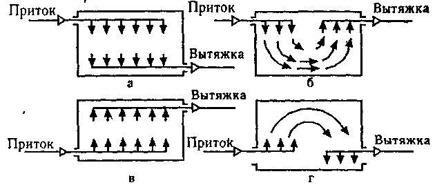
The quality of ventilation depends on the volume of passing air masses and the trajectory of their movement. The most favorable option is when the windows and doors are located at opposite ends of the room. In this case, when air circulates, it is completely replaced throughout the room.
Exhaust ducts are placed in rooms with the highest level of pollution, unpleasant odors and humidity - kitchens, bathrooms. Supply air comes from other rooms and pushes exhaust air out into the street.
In order for the hood to work in the desired mode, its top must be 0.5-1 m above the roof of the house. This creates the necessary pressure difference to move air.
Natural ventilation is silent, does not consume electricity, and does not require large investments in the device. Air masses penetrating from outside do not acquire additional properties- are not heated, not cleaned or moistened.
Air recirculation is limited to one apartment. There should be no suction from neighboring rooms.
Forced ventilation began to be used from the mid-19th century. At first, large fans were used in mines, in the holds of ships, and in drying shops. With the advent electric motors There has been a revolution in indoor ventilation. Adjustable devices have appeared not only for industrial, but also for domestic needs.

Now, when passing through a forced ventilation system, outside air is given additional valuable qualities - it is purified, humidified or dried, ionized, heated or cooled.
Fans and ejectors move large volumes of air masses over large areas. The system includes electric motors, dust collectors, heaters, noise suppressors, control and automation devices. They are built into air ducts.
Video description
More information about calculating ventilation with a recuperator is described in this video:
Calculation of natural ventilation of residential premises
The calculation consists of determining the supply air flow L during the cold and warm periods of the year. Knowing this value, you can select the cross-sectional area of the air ducts.
A house or apartment is considered as a single air volume where gases circulate through open doors or canvas trimmed 2 cm from the floor.
The influx occurs through leaky windows, external fences and by ventilation, removal occurs through exhaust ventilation ducts.

The volume is found using three methods - multiplicity, sanitary standards and squares. The largest is selected from the obtained values. Before calculating ventilation, the purpose and characteristics of all rooms are determined.
Basic formula for the first calculation:
L=nхV, m³/h, where
- V is the volume of the room (the product of height and area),
- n - multiplicity determined according to SNiP 2.08.01-89 depending on the calculated temperature in the room in winter.
According to the second method, the volume is calculated based on the specific norm per person, regulated by SNiP 41-01-2003. They take into account the number of permanently residing people, the presence gas stove and a bathroom. According to Table M1, the flow rate is 60 m³/person per hour.
The third method is by area.
- A - room area, m²,
- k- standard flow rate per m².
Calculation of the ventilation system: example
Three-room house with a total area of 80 m². The height of the premises is 2.7 m. Three people live.
- Living room 25 m²,
- bedroom 15 m²,
- bedroom 17 m²,
- bathroom - 1.4² m²,
- bath - 2.6 m²,
- kitchen 14 m² with four-burner stove,
- corridor 5 m².
Separately find the flow rate for inflow and exhaust so that the volume of incoming air is equal to the amount removed.
- living room L=25x3=75m³/h, multiplicity according to SNiP.
- bedrooms L=32x1=32 m³/h.
Total inflow flow:
L total=Lguest.+Lsleeping=75+32=107 m³/h.
- bathroom L= 50 m³/hour (tab.SNiP 41-01-2003),
- bath L= 25 m³/hour.
- kitchen L=90 m³/hour.
The inflow corridor is not standardized.
By hood:
L=Lkitchen+Lbathroom+L baths=90+50+25=165 m³/h.
The supply flow is less than the exhaust. For further calculations, the largest value L=165 m³/h is accepted.
According to sanitary standards, calculations are carried out based on the number of residents. Specific consumption per person is 60 m³.
L total=60x3=180m/h.
Taking into account temporary visitors, for whom the established air flow is 20 m3/h, we can take L = 200 m³/h.
By area, the flow rate is determined taking into account the standard air exchange rate of 3 m²/hour per 1 m² of living space.
L=57x3=171 m³/h.
According to the calculation results, the consumption according to sanitary standards is 200 m³/h, the multiplicity is 165 m³/h, and the area is 171 m³/h. Although all options are correct, the first option will make the conditions more comfortable for residents.
Bottom line
Knowing the air balance of a residential building, the size of the cross-section of the air ducts is selected. Most often, rectangular channels with an aspect ratio of 3:1 or round are used.
 <
<
To conveniently calculate the cross-section, you can use an online calculator or a diagram that takes into account the speed and air flow.
For natural ventilation, the speed in the main and branch air ducts is assumed to be 1 m/h. In the forced system, 5 and 3 m/h, respectively.
With a required air exchange of 200 m3/h, it is sufficient to implement a natural ventilation system. For large volumes of transported air, mixed recirculation is used. Devices designed for performance are installed in the channels, which will provide the necessary microclimate parameters.
If the ventilation in a house or apartment does not cope with its tasks, then this is fraught with very serious consequences. Yes, problems in the operation of this system do not appear as quickly and sensitively as, say, problems with heating, and not all owners pay adequate attention to them. But the results can be very sad. This is stale, waterlogged indoor air, that is, an ideal environment for the development of pathogens. These are foggy windows and damp walls, on which pockets of mold may soon appear. Finally, this is simply a decrease in comfort due to odors spreading from the bathroom, bathroom, kitchen into the living area.
To avoid stagnation, air must be exchanged at a certain frequency in the premises over a period of time. The inflow is carried out through the living area of the apartment or house, the exhaust through the kitchen, bathroom, toilet. This is why windows (vents) of exhaust ventilation ducts are located there. Often, homeowners who are undertaking renovations ask whether it is possible to seal up these vents or reduce them in size in order, for example, to install certain pieces of furniture on the walls. So, it is definitely impossible to completely block them, but transfer or change in size is possible, but not only with the condition that the necessary performance will be ensured, that is, the ability to pass the required volume of air. How can we determine this? We hope that the following calculators for calculating the cross-sectional area of an exhaust ventilation vent will help the reader.
Calculators will be accompanied by the necessary explanations for performing the calculations.
Calculation of normal air exchange for effective ventilation of an apartment or house
So, during normal ventilation operation, the air in the rooms should constantly change within an hour. The current governing documents (SNiP and SanPiN) establish standards for the flow of fresh air into each of the premises of the residential area of the apartment, as well as the minimum volumes of its exhaust through channels located in the kitchen, in the bathroom, and sometimes in some other special rooms.
| Room type | Minimum air exchange rates (multiplicity per hour or cubic meters per hour) | |
|---|---|---|
| INFLOW | HOOD | |
| Requirements for the Code of Rules SP 55.13330.2011 to SNiP 31-02-2001 “Single-apartment residential buildings” | ||
| Residential premises with permanent occupancy | At least one volume exchange per hour | - |
| Kitchen | - | 60 m³/hour |
| Bathroom, toilet | - | 25 m³/hour |
| Other premises | At least 0.2 volumes per hour | |
| Requirements for the Code of Rules SP 60.13330.2012 to SNiP 41-01-2003 “Heating, ventilation and air conditioning” | ||
| Minimum outdoor air flow per person: residential premises with permanent occupancy, under natural ventilation conditions: | ||
| With a total living area of more than 20 m² per person | 30 m³/hour, but not less than 0.35 of the total air exchange volume of the apartment per hour | |
| With a total living area of less than 20 m² per person | 3 m³/hour for every 1 m² of room area | |
| Requirements for the Code of Rules SP 54.13330.2011 to SNiP 31-01-2003 “Residential multi-apartment buildings”
|
||
| Bedroom, children's room, living room | One-time volume exchange per hour | |
| Office, library | 0.5 of volume per hour | |
| Linen room, pantry, dressing room | 0.2 of volume per hour | |
| Home gym, billiard room | 80 m³/hour | |
| Kitchen with electric stove | 60 m³/hour | |
| Premises with gas equipment | One-time exchange + 100 m³/hour for a gas stove | |
| A room with a solid fuel boiler or stove | One-time exchange + 100 m³/hour for a boiler or furnace | |
| Home laundry, dryer, ironing | 90 m³/hour | |
| Shower, bath, toilet or combined bathroom | 25 m³/hour | |
| Home sauna | 10 m³/hour per person | |
An inquisitive reader will probably notice that the standards for different documents are somewhat different. Moreover, in one case the standards are established solely by the size (volume) of the room, and in the other - by the number of people constantly staying in this room. (The concept of permanent stay means staying in the room for 2 hours or more).
Therefore, when carrying out calculations, it is advisable to calculate the minimum volume of air exchange according to all available standards. And then choose the result with the maximum indicator - then there will definitely be no errors.
The first calculator offered will help you quickly and accurately calculate the air flow for all rooms of an apartment or house.
Calculator for calculating the required air flow volumes for normal ventilation
Designing ventilation for a residential, public or industrial building takes place in several stages. Air exchange is determined based on regulatory data, the equipment used and the individual wishes of the customer. The scope of the project depends on the type of building: a one-story residential building or apartment is calculated quickly, with a minimum number of formulas, but serious work is required for a production facility. The methodology for calculating ventilation is strictly regulated, and the initial data is specified in SNiP, GOST and SP.
The selection of the optimal air exchange system in terms of power and cost is carried out step by step. The design order is very important, since the efficiency of the final product depends on its observance:
- Determination of the type of ventilation system. The designer analyzes the source data. If you need to ventilate a small living space, then the choice falls on a supply and exhaust system with natural impulse. This will be enough when the air flow is small and there are no harmful impurities. If you need to calculate a large ventilation complex for a factory or public building, then preference is given to mechanical ventilation with the function of heating/cooling the inlet, and if necessary, then with calculations based on hazards.
- Outlier analysis. This includes: thermal energy from lighting fixtures and machines; fumes from machines; emissions (gases, chemicals, heavy metals).
- Calculation of air exchange. The task of ventilation systems is to remove excess heat, moisture, and impurities from the room with an equilibrium or slightly different supply of fresh air. To do this, the air exchange rate is determined, according to which the equipment is selected.
- Selection of equipment. Produced according to the obtained parameters: required volume of air for supply/exhaust; indoor temperature and humidity; the presence of harmful emissions, ventilation units or ready-made multi-complexes are selected. The most important parameter is the volume of air required to maintain the design expansion ratio. Filters, heaters, recuperators, air conditioners and hydraulic pumps are used as additional network devices that ensure air quality.
Emissions calculation
The volume of air exchange and the intensity of the system depend on these two parameters:
- Standards, requirements and recommendations prescribed in SNiP 41-01-2003 “Heating, ventilation and air conditioning”, as well as other, more highly specialized regulatory documentation.
- Actual emissions. They are calculated using special formulas for each source and are shown in the table:
|
Heat release, J |
||
| Electric motor | N – nominal motor power, W; K1 – load factor 0.7-0.9 k2η - work coefficient at one time 0.5-1. |
|
| Lighting devices | ||
| Human | n – estimated number of people for this room; q is the amount of heat released by the body of one person. Depends on air temperature and work intensity. |
|
| Pool surface | 
|
V – speed of air movement over the water surface, m/s; T – water temperature, 0 C F – water surface area, m2 |
|
Moisture release, kg/h |
||
| Water surface, such as a swimming pool | P - mass transfer coefficient; F-evaporation surface area, m 2 ; Рн1, Рн2 - partial pressures of saturated water vapor at a certain temperature of water and air in the room, Pa; RB – barometric pressure. Pa. |
|
| Wet floor | F - wet floor surface area, m2; t s, t m – temperatures of air masses, measured by dry/wet thermometer, 0 C. |
|
Using the data obtained as a result of calculating harmful emissions, the designer continues to calculate the parameters of the ventilation system.
Air exchange calculation
Experts use two main schemes:
- According to aggregated indicators. This technique does not involve harmful emissions such as heat and water. Let's call it “Method No. 1”.
- Method taking into account excess heat and moisture. Conventional name “Method No. 2”.
Method No. 1
 The unit of measurement is m 3 / h (cubic meters per hour). Two simplified formulas are used:
L=K ×V(m 3 /h); L=Z ×n (m 3 / h), where
K – air exchange rate. The ratio of the air supply volume in one hour to the total air in the room, times per hour;
V – volume of the room, m3;
Z – value of specific air exchange per unit of rotation,
n – number of units of measurement.
The selection of ventilation grilles is carried out according to a special table. The selection also takes into account the average speed of air flow through the channel.

Method No. 2
The calculation takes into account the assimilation of heat and moisture. If there is excess heat in an industrial or public building, then the formula is used:
where ΣQ is the sum of heat releases from all sources, W;
с – thermal capacity of air, 1 kJ/(kg*K);
tyx – temperature of air directed to the exhaust, °C;
tnp - temperature of air directed to the inlet, °C;
Exhaust air temperature:
where tp.3 is the standard temperature in the work area, 0 C;
ψ - temperature increase coefficient, depending on the measurement height, equal to 0.5-1.5 0 C/m;
H – arm length from the floor to the middle of the hood, m.
When the technological process involves the release of a large volume of moisture, a different formula is used:
where G is the volume of moisture, kg/h;
dyx and dnp – water content per kilogram of dry supply and exhaust air.
There are several cases, described in more detail in the regulatory documentation, when the required air exchange is determined by the multiplicity:
k – frequency of indoor air changes, once per hour;
V is the volume of the room, m3.
Section calculation
The cross-sectional area of the duct is measured in m2. It can be calculated using the formula:
where v is the speed of air masses inside the channel, m/s.
It varies for main air ducts 6-12 m/s and side appendages no more than 8 m/s. Quadrature affects the channel capacity, the load on it, as well as the noise level and installation method.
Calculation of pressure loss
The walls of the air duct are not smooth, and the internal cavity is not filled with vacuum, so part of the energy of the air masses during movement is lost to overcome these resistances. The amount of loss is calculated using the formula:
where ג is friction resistance, defined as:
The formulas given above are correct for channels with a circular cross-section. If the duct is square or rectangular, then there is a formula for converting to an equivalent diameter:
where a,b are the dimensions of the channel sides, m.
Pressure and engine power
The air pressure from the blades H must completely compensate for the pressure loss P, while creating the calculated dynamic P d at the outlet.
Electric fan motor power:
Selection of heater
Often heating is integrated into the ventilation system. For this purpose, air heaters are used, as well as the recirculation method. The choice of device is carried out according to two parameters:
- Q in – maximum consumption of thermal energy, W/h;
- F k – determination of the heating surface for the heater.
Calculation of gravitational pressure
Can only be used for natural ventilation systems. With its help, its performance is determined without mechanical stimulation.
Selection of equipment
Based on the data obtained on air exchange, the shape and size of the cross-section of air ducts and grilles, the amount of energy for heating, the main equipment is selected, as well as fittings, a deflector, adapters and other related parts. Fans are selected with a power reserve for peak operating periods, air ducts are selected taking into account the aggressiveness of the environment and ventilation volumes, and air heaters and recuperators are selected based on the thermal demands of the system.
Design errors
At the project creation stage, errors and shortcomings are often encountered. This could be reverse or insufficient draft, blowing (upper floors of multi-storey residential buildings) and other problems. Some of them can be solved after installation is completed, using additional installations.
A striking example of low-skilled calculation is insufficient exhaust draft from a production facility without particularly harmful emissions. Let's say the ventilation duct ends in a round shaft, rising 2,000 - 2,500 mm above the roof. Raising it higher is not always possible or advisable, and in such cases the principle of flare emission is used. A tip with a smaller working hole diameter is installed in the upper part of the round ventilation shaft. An artificial narrowing of the cross-section is created, which affects the rate of gas release into the atmosphere - it increases many times over.

The method for calculating ventilation allows you to obtain a high-quality internal environment by correctly assessing the negative factors that worsen it. The Mega.ru company employs professional designers of engineering systems of any complexity. We provide services in Moscow and neighboring regions. The company also successfully engages in remote collaboration. All communication methods are listed on the page, please contact us.
- System performance serving up to 4 rooms.
- Dimensions of air ducts and air distribution grilles.
- Resistance of the air network.
- Heater power and estimated energy costs (when using an electric heater).
If you need to choose a model with humidification, cooling or recovery, use the calculator on the Breezart website.
An example of calculating ventilation using a calculator
Using this example, we will show how to calculate the supply ventilation for a 3-room apartment in which a family of three lives (two adults and a child). During the day, sometimes relatives come to visit them, so up to 5 people can stay in the living room for a long time. The ceiling height of the apartment is 2.8 meters. Room parameters:
We will set the consumption rates for the bedroom and nursery in accordance with the recommendations of SNiP - 60 m³/h per person. For the living room, we will limit ourselves to 30 m³/h, since there are rarely a large number of people in this room. According to SNiP, such air flow is permissible for rooms with natural ventilation (you can open a window for ventilation). If we set the air flow rate of 60 m³/h per person for the living room, then the required productivity for this room would be 300 m³/h. The cost of electricity to heat this amount of air would be very high, so we made a compromise between comfort and efficiency. To calculate the air exchange rate for all rooms, we will select a comfortable double air exchange.
The main air duct will be rectangular, rigid, and the branches will be flexible, sound-insulated (this combination of duct types is not the most common, but we chose it for demonstration purposes). For additional purification of the supply air, a fine dust filter of class EU5 will be installed (we will calculate the network resistance with dirty filters). We will leave the air velocities in the air ducts and the permissible noise level on the grilles equal to the recommended values, which are set by default.
We begin the calculation by drawing up a diagram of the air distribution network. This diagram will allow us to determine the length of the air ducts and the number of turns that can be in both horizontal and vertical planes (we need to count all turns at right angles). So, our scheme:
The resistance of the air distribution network is equal to the resistance of the longest section. This section can be divided into two parts: the main air duct and the longest branch. If you have two branches of approximately the same length, then you need to determine which one has more resistance. To do this, we can assume that the resistance of one turn is equal to the resistance of 2.5 meters of the air duct, then the greatest resistance will be the branch whose value (2.5 * number of turns + length of the air duct) is maximum. It is necessary to separate two parts from the route so that you can set different types of air ducts and different air speeds for the main section and branches.
In our system, balancing throttle valves are installed on all branches, allowing you to adjust the air flow in each room in accordance with the project. Their resistance (in the open state) has already been taken into account, since this is a standard element of the ventilation system.
The length of the main air duct (from the air intake grille to the branch to room No. 1) is 15 meters; there are 4 turns at right angles in this section. The length of the air supply unit and the air filter can be ignored (their resistance will be taken into account separately), and the resistance of the silencer can be taken equal to the resistance of the air duct of the same length, that is, simply consider it part of the main air duct. The longest branch is 7 meters long and has 3 right angle turns (one at the branch, one at the duct and one at the adapter). Thus, we have specified all the necessary initial data and can now begin calculations (screenshot). The calculation results are summarized in tables:
Calculation results for premisesResults of calculation of general parameters
| Ventilation system type | Regular | VAV |
| Performance | 365 m³/h | 243 m³/h |
| Cross-sectional area of the main air duct | 253 cm² | 169 cm² |
| Recommended dimensions of the main air duct | 160x160 mm 90x315 mm 125x250 mm |
125x140 mm 90x200 mm 140x140 mm |
| Air network resistance | 219 Pa | 228 Pa |
| Heater power | 5.40 kW | 3.59 kW |
| Recommended air supply installation | Breezart 550 Lux (in 550 m³/h configuration) |
Breezart 550 Lux (VAV) |
| Maximum performance recommended PU |
438 m³/h | 433 m³/h |
| Electric power heater PU | 4.8 kW | 4.8 kW |
| Average monthly electricity costs | 2698 rubles | 1619 rubles |
Air duct network calculation
- For each room (subsection 1.2), the productivity is calculated, the cross-section of the air duct is determined and a suitable air duct of standard diameter is selected. Using the Arktos catalog, the dimensions of distribution grilles with a given noise level are determined (data for the AMN, ADN, AMP, ADR series is used). You can use other grilles with the same dimensions - in this case, there may be a slight change in the noise level and network resistance. In our case, the grilles for all rooms turned out to be the same, since at a noise level of 25 dB(A) the permissible air flow through them is 180 m³/h (there are no smaller grilles in these series).
- The sum of the air flow rates for all three rooms gives us the overall system performance (subsection 1.3). When using a VAV system, the system performance will be one third lower due to separate adjustment of air flow in each room. Next, the cross-section of the main air duct is calculated (in the right column - for a VAV system) and appropriately sized rectangular air ducts are selected (usually several options are given with different aspect ratios). At the end of the section, the resistance of the air network is calculated, which turns out to be quite large - this is due to the use of a fine filter in the ventilation system, which has a high resistance.
- We have received all the necessary data to complete the air distribution network, with the exception of the size of the main air duct between branches 1 and 3 (this parameter is not calculated in the calculator, since the network configuration is unknown in advance). However, the cross-sectional area of this section can be easily calculated manually: from the cross-sectional area of the main air duct, you need to subtract the cross-sectional area of branch No. 3. Having obtained the cross-sectional area of the air duct, its size can be determined by.
Calculation of heater power and selection of air handling unit
The recommended model Breezart 550 Lux has software-configurable parameters (performance and heater power), so the performance that should be selected when setting up the control unit is indicated in brackets. It can be noted that the maximum possible heater power of this unit is 11% lower than the calculated value. The lack of power will be noticeable only when the outside temperature is below -22°C, and this does not happen often. In such cases, the air handling unit will automatically switch to a lower speed to maintain the set outlet temperature (“Comfort” function).
The calculation results, in addition to the required performance of the ventilation system, indicate the maximum performance of the control unit at a given network resistance. If this performance turns out to be significantly higher than the required value, you can use the ability to programmatically limit the maximum performance, which is available for all Breezart ventilation units. For a VAV system, the maximum capacity is provided for reference only, as performance is adjusted automatically while the system is running.
Operating cost calculation
This section calculates the cost of electricity spent on heating air during the cold season. The costs for a VAV system depend on its configuration and operating mode, therefore they are assumed to be equal to the average value: 60% of the costs of a conventional ventilation system. In our case, you can save money by reducing air consumption in the living room at night and in the bedroom during the day.
|
|
|
|
Although there are many programs for ventilation calculations, many parameters are still determined the old fashioned way, using formulas. Calculation of the ventilation load, area, power and parameters of individual elements is carried out after drawing up the diagram and distribution of the equipment.
This is a difficult task that only professionals can do. But if you need to calculate the area of some ventilation elements or the cross-section of air ducts for a small cottage, you can really do it yourself.
Air exchange calculation
If there are no toxic emissions in the room or their volume is within acceptable limits, air exchange or ventilation load is calculated using the formula:
R= n * R1,
Here R1– air requirement of one employee, in cubic meters per hour, n– the number of permanent employees in the premises.
If the volume of the room per employee is more than 40 cubic meters and natural ventilation is working, there is no need to calculate air exchange.
For domestic, sanitary and utility premises, ventilation calculations based on hazards are made based on approved air exchange rate standards:
- for administrative buildings (exhaust) – 1.5;
- halls (serving) – 2;
- conference rooms for up to 100 people with a capacity (for supply and exhaust) - 3;
- rest rooms: supply 5, exhaust 4.
For industrial premises in which hazardous substances are constantly or periodically released into the air, ventilation calculations are made based on hazardous substances.
Air exchange by pollutants (vapors and gases) is determined by the formula:
Q= K\(k2- k1),
Here TO– the amount of steam or gas appearing in the building, in mg/h, k2– vapor or gas content in the outflow, usually the value is equal to the maximum permissible concentration, k1– gas or steam content in the inlet.
The concentration of harmful substances in the inlet is allowed to be up to 1/3 of the maximum permissible concentration.
For rooms with the release of excess heat, air exchange is calculated using the formula:
Q= Ghut\c(tyx – tn),
Here Gizb– excess heat drawn out is measured in W, With– specific heat capacity by mass, s=1 kJ, tyx– temperature of air removed from the room, tn– inlet temperature.
Heat load calculation

Calculation of the thermal load on ventilation is carried out according to the formula:
Qin=Vn*k * p * Cp(tvn –tnro),
in the formula for calculating the thermal load on ventilation Vн– external volume of the building in cubic meters, k– air exchange rate, tvn– average temperature in the building, in degrees Celsius, tnro– outside air temperature used in heating calculations, in degrees Celsius, r– air density, in kg/cubic meter, Wed– heat capacity of air, in kJ/cubic meter Celsius.
If the air temperature is lower tnro the air exchange rate is reduced, and the heat consumption rate is considered equal to Qв, a constant value.
If, when calculating the heat load for ventilation, it is impossible to reduce the air exchange rate, the heat consumption is calculated based on the heating temperature.
Heat consumption for ventilation
The specific annual heat consumption for ventilation is calculated as follows:
Q= * b * (1-E),
in the formula for calculating heat consumption for ventilation Qo– total heat loss of the building during the heating season, Qb– domestic heat inputs, Qs– heat input from outside (sun), n– coefficient of thermal inertia of walls and ceilings, E– reduction factor. For individual heating systems 0,15 , for central 0,1 , b– heat loss coefficient:
- 1,11 – for tower buildings;
- 1,13 – for multi-section and multi-entry buildings;
- 1,07 – for buildings with warm attics and basements.
Calculation of duct diameter

The diameters and cross-sections of ventilation air ducts are calculated after the general diagram of the system has been drawn up. When calculating the diameters of ventilation air ducts, the following indicators are taken into account:
- Air volume (supply or exhaust air), which must pass through the pipe in a given period of time, cubic meters per hour;
- Air speed. If, when calculating ventilation pipes, the flow rate is underestimated, air ducts with a cross-section that are too large will be installed, which entails additional costs. Excessive speed leads to vibrations, increased aerodynamic hum and increased equipment power. The speed of movement on the inflow is 1.5 - 8 m/sec, it varies depending on the area;
- Ventilation pipe material. When calculating the diameter, this indicator affects the wall resistance. For example, black steel with rough walls has the highest resistance. Therefore, the calculated diameter of the ventilation duct will have to be slightly increased compared to the standards for plastic or stainless steel.
Table 1. Optimal air flow speed in ventilation pipes.
When the throughput of future air ducts is known, the cross-section of the ventilation duct can be calculated:
S= R\3600 v,
Here v– speed of air flow, in m/s, R– air consumption, cubic meters/h.
The number 3600 is a time coefficient.
![]()
Here: D– diameter of the ventilation pipe, m.
Calculation of the area of ventilation elements
Calculation of the ventilation area is necessary when the elements are made of sheet metal and it is necessary to determine the quantity and cost of the material.
The ventilation area is calculated using electronic calculators or special programs; many of them can be found on the Internet.
We will provide several tabular values of the most popular ventilation elements.
| Diameter, mm | Length, m | |||
| 1 | 1,5 | 2 | 2,5 | |
| 100 | 0,3 | 0,5 | 0,6 | 0,8 |
| 125 | 0,4 | 0,6 | 0,8 | 1 |
| 160 | 0,5 | 0,8 | 1 | 1,3 |
| 200 | 0,6 | 0,9 | 1,3 | 1,6 |
| 250 | 0,8 | 1,2 | 1,6 | 2 |
| 280 | 0,9 | 1,3 | 1,8 | 2,2 |
| 315 | 1 | 1,5 | 2 | 2,5 |
Table 2. Area of straight air ducts of circular cross-section.
Area value in sq. m. at the intersection of horizontal and vertical stitching.
| Diameter, mm | Angle, degrees | ||||
| 15 | 30 | 45 | 60 | 90 | |
| 100 | 0,04 | 0,05 | 0,06 | 0,06 | 0,08 |
| 125 | 0,05 | 0,06 | 0,08 | 0,09 | 0,12 |
| 160 | 0,07 | 0,09 | 0,11 | 0,13 | 0,18 |
| 200 | 0,1 | 0,13 | 0,16 | 0,19 | 0,26 |
| 250 | 0,13 | 0,18 | 0,23 | 0,28 | 0,39 |
| 280 | 0,15 | 0,22 | 0,28 | 0,35 | 0,47 |
| 315 | 0,18 | 0,26 | 0,34 | 0,42 | 0,59 |
Table 3. Calculation of the area of bends and half-bends of circular cross-section.
Calculation of diffusers and grilles

Diffusers are used to supply or remove air from a room. The cleanliness and temperature of the air in every corner of the room depends on the correct calculation of the number and location of ventilation diffusers. If you install more diffusers, the pressure in the system will increase and the speed will drop.
The number of ventilation diffusers is calculated as follows:
N= R\(2820 * v *D*D),
Here R– throughput, in cubic meters per hour, v– air speed, m/s, D– diameter of one diffuser in meters.
The number of ventilation grilles can be calculated using the formula:
N= R\(3600 * v * S),
Here R– air flow in cubic meters per hour, v– air speed in the system, m/s, S– cross-sectional area of one grating, sq.m.
Calculation of a duct heater

The calculation of an electric ventilation heater is carried out as follows:
P= v * 0,36 * ∆ T
Here v– volume of air passed through the heater in cubic meters per hour, ∆T– the difference between the air temperature outside and inside, which must be provided by the heater.
This indicator varies from 10 to 20, the exact figure is set by the client.
Calculation of a heater for ventilation begins with calculating the frontal cross-sectional area:
Af=R * p\3600 * Vp,
Here R– volume of inlet flow, cubic meters per hour, p– density of atmospheric air, kg\cub.m, Vp– mass air velocity in the area.
The cross-sectional size is necessary to determine the dimensions of the ventilation heater. If, according to calculations, the cross-sectional area turns out to be too large, it is necessary to consider the option of a cascade of heat exchangers with a total calculated area.
The mass velocity indicator is determined through the frontal area of the heat exchangers:
Vp= R * p\3600 * Af.fact
To further calculate the ventilation heater, we determine the amount of heat required to warm the air flow:
Q=0,278 * W * c (Tp-Ty),
Here W– warm air consumption, kg/hour, Tp– supply air temperature, degrees Celsius, That– outdoor air temperature, degrees Celsius, c– specific heat capacity of air, constant value 1.005.
Since fans in supply systems are placed in front of the heat exchanger, we calculate the flow of warm air as follows:
W= R*p
When calculating the ventilation heater, you should determine the heating surface:
Apn=1.2Q\ k(Ts.t-Ts.v),
Here k– heat transfer coefficient of the heater, Ts.t– average coolant temperature, in degrees Celsius, Ts.v– average inlet temperature, 1,2 – cooling coefficient.
Calculation of displacement ventilation
With displacement ventilation, calculated upward air flows are installed in the room in places of increased heat generation. Cool, clean air is supplied from below, which gradually rises and is removed to the outside in the upper part of the room along with excess heat or moisture.
When properly calculated, displacement ventilation is much more effective than mixing ventilation in the following types of rooms:
- halls for visitors in catering establishments;
- conference rooms;
- any halls with high ceilings;
- student audiences.
Calculated ventilation displaces less effectively if:
- ceilings below 2m 30 cm;
- the main problem of the room is increased heat generation;
- it is necessary to lower the temperature in rooms with low ceilings;
- there are powerful air turbulences in the hall;
- the temperature of the hazards is lower than the air temperature in the room.
Displacement ventilation is calculated based on the fact that the thermal load on the room is 65 - 70 W/sq.m, with a flow rate of up to 50 liters per cubic meter of air per hour. When heat loads are higher and flow rates are lower, it is necessary to organize a mixing system combined with cooling from above.