Self-installation electrical panel in the apartment - good decision. At the very least, you won’t have to limit the need to develop your own electrical supply scheme for the apartment by the lack of free space in the access panel. And it definitely won’t be enough, since most houses were built according to outdated designs, and no one imagined that in the future we would have such a variety of household appliances.
Moreover, individual (powerful) devices require their own connection lines and various protective devices in the form of individual circuit breakers, RCDs or differential circuit breakers. It all comes down to assembling the electrical panel. And not just complete it, but install it correctly. How to do this is the topic of the article.
What to consider when installing the shield
There are still shields of the old modification on sale, in which “sockets” are mounted for installing so-called “plugs” (disposable or automatic fuses). There is no fundamental difference, but since the dimensions of modern boxes are somewhat smaller and the safety class is higher, the choice, especially for an apartment, is obvious.
There are two types of shields - built-in and wall-mounted. The first ones are recommended for hidden wiring, therefore, they are suitable for apartment schemes. The question just arises - how to create a niche for such a box if there is none? No one will chisel masonry or reinforced concrete products - that’s understandable. Therefore, you should purchase a hinged shield. It’s not hard to figure out how to connect the wires to it. Available for sale various types connecting products (boxes, blocks, adapters), so this problem is solvable.
Buying an electrical panel based on the current day is not entirely rational. Any scheme undergoes changes, and there is no guarantee that the apartment will not soon be replenished with a new acquisition in the form of some type of equipment, for which it will be necessary to install another personal line with the installation of additional and AV.
Or the old model will be replaced by a more advanced one with increased power. It is not a fact that the previous protective devices on this line will correspond in their characteristics to the changed parameters of the circuit. Consequently, these products will also have to be changed, and the dimensions of the new ones may turn out to be larger. Will it be possible to place them in an existing apartment electrical panel, taking into account its already dense layout?
But the recommendations found on the Internet to install several spare machines and RCDs in advance are, for the future, very doubtful. Which products exactly? At what current? Is it worth spending money if it is still unknown whether their characteristics are suitable for connecting a new line.
The installation location of the box is chosen so that you can freely approach it, without any delays. It is rare, but it also happens that the circuit breaker simply does not work, and it has to be turned off manually. By the way, if, to assemble an electrical panel, the owner, in order to save money, focuses on cheap machines, and even those of dubious origin, he needs to be prepared for this a priori. Or vice versa - the AV has worked, and after eliminating the defect on the line, it needs to be turned on again.
Rules for assembling an apartment electrical panel
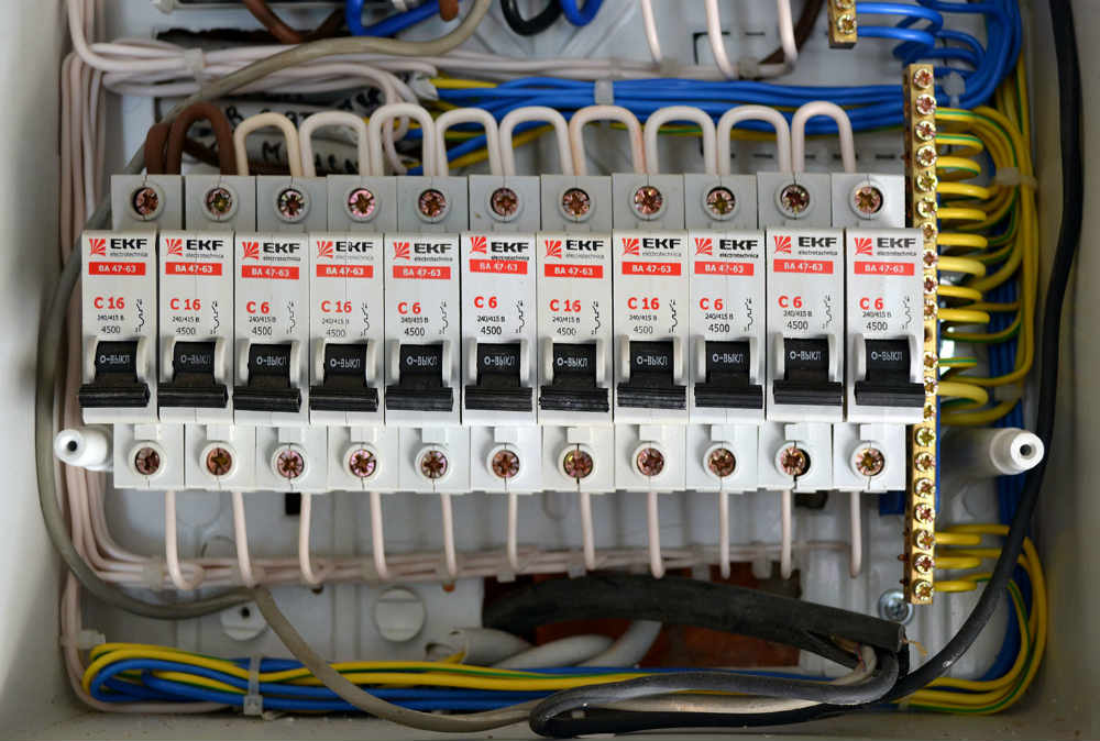
The input (central) machine is always placed at the top left. If the panel also provides for the placement of an electric meter, then to the right of it (an example is shown in the photo). It should be understood that only a place is marked for the meter, and it is installed only after the panel has been assembled and all connections have been made. That is, immediately before. Otherwise, there is a risk of breaking the factory seal. No one will register the device in this form, even if it does not have any damage. This means you will have to buy a new one.

The connection lines for sockets and lighting must be “untied”. Each has its own machine gun. If the apartment has powerful household installations, then for one sample - your own personal AV, connected separately, directly from the central output. A properly designed indoor electrical circuit takes this into account.
In addition to the DIN rails, the electrical panel must have a grounding block. Boxes are sold in various configurations, often in the form of an empty box, which is assembled from scratch. It is easy to visually distinguish the ground bus from the mounting strips - by color (yellowish tint of the metal), shape (narrow, elongated) and the presence of sockets (for connecting wires) and clamping screws. If it is not known according to what scheme the power supply is organized apartment building, then when assembling the electrical panel, you should install 2 blocks - for “ground” and “zero”.
Correct assembly of the box also includes the application of explanatory notes. In the absence of " home handyman“Any member of the household should be able to easily figure out where each machine is installed. And your own memory can sometimes fail you. Simple marking with alphabetic or numeric symbols is the most common option, given that there is little free space in the electrical panel, and applying full inscriptions is by definition impossible. Therefore, it is enough just to make a table symbols and stick it on inner side box doors. The author did just that. It’s convenient and understandable to all family members.
In order to save usable space and reduce the dimensions of the box, in some cases it is advisable to replace the AB - RCD pairs with 1 differential circuit breaker. About such protective devices.
All protective devices are mounted on DIN rails so that the “input” terminals are located at the top. Accordingly, below is the “exit”.
Several of the most common scheme options will help you understand correct assembly apartment electrical panel.

Correctly assembling an electrical apartment panel is possible only if a competent electrical wiring diagram has been developed, taking into account comprehensive circuit protection. Installation work It's easy to do on your own. Here the skills of a professional do not play a big role.
The main thing is attentiveness and accuracy. But it is better to entrust the drawing up of the diagram to a specialist, since you will need not only a drawing, but also an accurate calculation of all its parameters. If you have no understanding of electrical engineering, then you should not take on this work yourself. And even more so, do not copy the layout and connection of panels installed in the apartments of friends, acquaintances, and the like. This won't end well.

There are certain requirements for the location for installing an electrical panel in an apartment. Although this is not directly related to the topic of the article, it would be useful to remind you of them.
- Firstly, at a level of at least 150 cm from the floor covering.
- Secondly, the maximum curvature of the base on which the box is attached is 1.50.
- Thirdly, the shield should be positioned as far as possible possible removal from engineering communications(gas and water supply). Minimum – 1.8 m.
- To make it easier to understand the electrical wiring inside the panel in the future, you should adhere to generally accepted standards. Wires are used for various circuits a certain color. Strength (phase) - red, zero - blue (blue), earth - yellow-green.
Note!
Connection power cable to the apartment's central circuit breaker is carried out after completing the assembly and checking the correct installation of the circuit.
See also video assembling a panel for an apartment:
Analysis of a home electrical panel diagram
Warm greetings from Taganrog to all my readers! People ask me – where did I go, and why are there no new articles?
Everything is fine with me, I just write a lot for other sites now. And to those who miss me especially much, I’ll say - come to my VK group SamElectric.ru, I’m there every day!
So, today’s article follows my detailed answer to reader Anton from Krasnodar. Anton assembles a home electrical panel with his own hands, remaking it from what he had. Naturally, he had several questions and turned to me. And he did the right thing.
I think that my answer and detailed analysis will help my other readers in drawing up a diagram and assembling a home panel.
I also highly recommend my similar articles, in which I consider and.
Below I publish a reader’s question regarding the electrical panel diagram; I will write my answers in quotations.
Diagram of the old electrical panel (Option 1)
Hello!
Subscribe! It will be interesting.
I would like to ask for your help and give me some of your time.
The house I bought is relatively old, and the saddest thing is that when it was built, the selection of specialists was terrible. Power supply diagram two-story house was depressing.

Old shield diagram, simplest (option 1)
Diagram of an old switchboard in a house:

Diagram of an old switchboard in a house
Everything is terribly sad and budgetary. But what’s most depressing is not the fact that the upper “bus” is assembled from exposed pieces of wire. And the fact that such shields rural areas(like Taganrog, not to mention Varenovka) are considered quite normal. Well, after two traffic jams, switching to automatic machines is chic!
Unfortunately, there is no photo left of the entrance panel, but it was also assembled anyhow.
An attempt to redesign the home panel diagram (Option 2)
So. The house was connected to one phase and had no grounding at all. At the moment, it is not possible to carry out work to replace all the wiring for certain reasons. But due to a minor reconstruction, it became possible to somehow bring the house’s electrics back to life and assemble a normal panel circuit.
Initially, the task was to connect 3 phases and assemble the input (street) switchboard. Realizing that a master is better than an amateur, at least based on experience, I involved our electrician in this task. Here is the result.

Introductory shield after alteration (option 2) – not with your own hands
Here is a diagram of the input switchboard plus the home switchboard, after alteration by a local electrician (option 2):

Scheme of the introductory and home switchboard after alteration, option 2
After inspecting the work, I had a lot of questions. Why such a generator connection diagram? Why are the multi-core wires connecting the automation not in the terminals? Why is there no RCD (I listened to a separate lecture about the suckers who install it and then suffer)?.. There was also no place for the grounding input. Maybe the level of the specialist was inappropriate. But I realized that I would have to do everything myself again.
Some questions still led me to a dead end (more on them at the end).
Completely redesigned scheme (Option 3)
First a diagram was made.

Diagram of the input panel, panel in the house and basement - option 3
It took into account that in the main part of the house the wiring (for now) will remain as it is. Existing and planned consumers were separated into phases. In connection with the renovation of one of the rooms, it was decided to remove a separate panel for the dining room, boiler room, sockets for the washing machine and electric stove. Wiring was carried out in a corrugation on the wall to the panel, and from the panel to consumers in the wall (on the ceiling, the lighting line cable was corrugated).
What's new in the VK group? SamElectric.ru ?
Subscribe and read the article further:
The cable from the VVGng(A) 5x6 input panel will be inserted into the house in a corrugated (street) structure. From the internal shield, a VVGng(A) 4x4 cable (two phases, zero and ground) goes along the wall in a corrugation to the second shield.
It is better to use a cable with a larger cross-section, especially if the length is more than 15 m. It is possible (current in each phase is more than 60A) and.
From it the cables (VVGng-P) go to consumers according to the diagram. The wires are laid in grooves (without corrugation), and on the ceiling in a corrugation.
Everything is correct.
In principle, the control panel in the house remained virtually unchanged due to the impossibility of going through all the wiring and dividing it into groups.
The calculation of the loads on the lines, in principle, turned out to be acceptable, except that in the old part of the house the load on two lines exceeded 25 A. The total load on the phase (~ 13 kW) was also baffling. Maybe I did the calculation wrong somehow?
Yes, there is such a thing, I write below.
As a result, at the moment I am at a dead end on a number of issues. I don’t want to do it anyhow (like “put a 16A machine here, that’s enough”)...
- Are the RCDs and machines selected correctly? Does it make sense to put instead of the link RCD automatic machine- automatic rifle?
- Is it possible to reduce the number of RCDs somewhere to reduce the cost?
In terms of price, differential is usually cheaper than a combination of RCD + Automatic. In addition, installing differentials saves space in the panel and simplifies installation. That's why I usually put them on. The disadvantage of the differential is that it is difficult to find out why it was knocked out - by leakage or overload. Another minus is that if you change it, it’s the entire differential, but if the automatic needs to be changed separately, then it’s cheaper in price. Therefore, the most correct, but most expensive option is a combination of RCD + Automatic. Moreover, for each line separately. But to save money, you can install one RCD, and then – circuit breakers of several lines. The disadvantage of such savings is that if there is a leak in one of the lines, the RCD will cut off all the lines. You need to think about what is the best option in this case. The permissible current of the RCD must be no less than the sum of the currents of all machines.
- Is the diagram drawn up correctly? (load distribution along lines is in the attached Excel file)
Where the wire has a cross-section of 2.5 - a 25 A circuit breaker - that's a lot! It should be set to 20A, or better (to guarantee protection of the electrical wiring) - 16A. Where there are no pumps and motors, it is better to install machines with characteristic B - they respond faster in case of short circuits and large overloads. This general recommendation for all groups.
Along the lines (everywhere currents with a utilization factor of 0.7)
A panel in the house that can be remade, but the wiring cannot: Check all connections in the distribution boxes and sockets (it is better to replace the sockets). When overloaded, twists and terminals burn first, cables last.
Phase A:
1. Street pump. Current 22A. Reduce the utilization coefficient (turn on one by one).
2. Garage. Current 25A. If possible, connect two circuit breakers to one RCD, and connect part of the load (for example, sockets) through a second circuit breaker and a second cable.
11. Pumping station. Current 17A. In terms of current, everything is OK, but I warn you - this is the place where the RCD will knock out most often!
The total current of Phase A is 64A, power is 14 kW.
Phase B:
7. Stove, oven. Current 34A. Since it is possible to use the line at 100% (for example, on holidays), this is a very important place. It is necessary to divide it into 2 lines (it is better to install 2 RCDs). Stove - via automatic 32A, cable 3x4, oven - automatic 20 A, cable - 3x2.5.
8. sockets 1. Current 18A. OK.
9. sockets 2. Current 13A. OK.
10. Dining room light. Current 3A. The machine can be set to 10A. Cable 3x1.5.
The total current of Phase B is 68A, power is 15 kW.
Phase C:
3. 2nd floor outlet. Current 34A. In reality, the current will be less, and it is also limited by cable overheating and a 25A circuit breaker. If possible, divide the line into two.
4. 1st floor hall. Current 10A. Here, even without a usage coefficient, you are asking for a 16A automatic
5. Kitchen. Current 32A. Like line 3 - In reality, the current will be less, and it is also limited by cable overheating and a 25A circuit breaker.
6. Reserve. Connect an unexpected powerful load here (a hammer drill on the street, etc.)
The total current of Phase C is 76A, power is 18 kW. In reality, perhaps less (like phase A, B).
It is better to connect the socket in the panel through a 16-25A circuit breaker - there will be both protection and prompt shutdown.
- According to the calculations, the nominal total power of the stabilizer was 30 kVA. It seems to me that I made a mistake again somewhere... Which stabilizer should I take?
According to the stabilizer. Why did you decide that it would be needed? What is the voltage situation in the area, what do the neighbors say? It is more important and cheaper to install lightning protection (SPD) and voltage relays, which will save in case of abnormal voltages.
If stabilizers are still needed, then these will be three stabilizers, 20 VA each. It is better to take electromechanical ones - they are more reliable, but require maintenance.
If it's not difficult, please help.
I am attaching photos and pictures, a diagram file for sPlan 7 (published at the end of the article) .
Best regards, Anton.
This is where the story ends.
PEN conductor separation
According to PUE 1.7.145, switching PE and PEN conductors is not allowed. Therefore, the PEN conductor coming from the street must be unbroken to the PE bus. Then it goes to bus N through the counter and RCD.
Therefore, the final diagram will look like this:

diagram 4 with correct separation of the PEN conductor
After the RCD, these two buses are not connected anywhere!
Notes on the generator
As for the generator, it’s a good idea, but you won’t be able to find a single-phase generator with a power of more than 45 kW, so the load when powered by the generator will have to be limited, and you will have to buy a generator with a capacity of 10-15 kW. It’s right that you didn’t use the automatic transfer switch, but switch it manually - it’s more reliable.
Danger of zero loss
By three-phase input. It is very important to control the places that I marked in the diagram. There, a break in the “three-phase” zero is possible; this accident will lead to equipment breakdowns. Recently there was such a case, the owner flew in for many thousands.
Panel diagram with zero switching from power sources
Fire RCD
According to the introductory “fire” RCD. A current of 32 Amps is not enough. You need an RCD or a 40 Ampere circuit breaker for guaranteed operation. For an RCD this is the operating current. It will not turn off if it is exceeded, but it will continue to work without overheating. And circuit breakers must protect against overload. In particular, the machine at the 32 Ampere input, in front of the meter, which is actually connected in series with the RCD.
I invite readers to discuss this home electrical panel diagram. I’m not the ultimate truth, and I might miss something.
Download files for the article
/ All loads are fully described and divided into phases, xlsx, 15.89 kB, downloaded: 115 times.// Schemes in Plan - all three options, zip, 58.44 kB, downloaded: 121 times./
/ With zero switching, zip, 82.12 kB, downloaded: 84 times./
Installation and assembly of the electrical panel - difficult work, requiring a clear sequence, where every action is important and does not tolerate neglect.
The main qualities of the device are safety and ease of use.
Purpose of the electrical panel:
- accounting for electricity consumption;
- circuit management;
- protection of the circuit from fire due to overload.
It is possible to install an electrical panel in a house, apartment or country house on your own, but to do this you need to have basic knowledge and skills as an electrician.
Electrical panel project
For a person who is far from electricity, it is better to start designing an electrical panel when the wiring installation is completely ready and the wires are brought to the location of the future electrical panel. First you need to draw up drawings for the work and select suitable components.
Consumer calculations
A complete list of consumers is compiled. To do this, you need to ignore devices like a fan or table lamp, and write down and number each wire connected to the panel. Sockets must be recorded separately, lighting - separately. High-power appliances (boilers, washing machines, air conditioners, electric stoves) require wiring protection from overload, so they are connected not through distribution boxes, but directly to the panel.
List of consumers for three-room apartment usually looks like this:
- sockets:
- bedroom;
- living room;
- children's;
- kitchen;
- bathroom;
- entrance hall and corridor.
- Washing machine;
- boiler;
- air conditioner;
- electric stove;
- lighting:
- bedroom;
- living room;
- children's;
- kitchen, bathroom;
- hallway, corridor.
All consumers are divided into groups (circuits) according to power consumption: sockets for household appliances in one room, things like an iron, sconce, TV and others can be combined into one group (sockets in one room - one group, in another - another), lighting - in the next, also by room. Each group has its own circuit breaker (or just a circuit breaker) on the panel, and for high-power appliances - washing machine, boiler, electric stove, air conditioner - there is one separately for each. Machines may also be called fuses or bags.
Important! Connection of low-power devices (TV, telephone, Internet, security) is carried out in a separate box!
Drawing up an electrical panel diagram
The electrical panel is a housing - metal or plastic box- with modules inside. A module is a component that occupies one installation “space” (within one DIN rail). Some devices can take up two or even three “places”.
For clarity, you should create a diagram according to which the shield will be assembled.
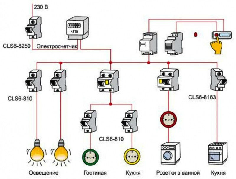
Examples of 220 V switchboard circuits:
- introductory machine;
- electric meter;
- RCD (residual current device);
- ground bus;
- "zero" bus;
- automatic sockets for high-power devices at 25 A;
- automatic socket group for household appliances of low and medium power at 25 A;
- automatic lighting 16 A;
- L—phase;
- N - zero;
- PE - grounding.

Each house or apartment will have its own layout in accordance with the preferences of the owners.
Selection of components
Depending on the position on the wall, the electrical panel can be of two types:
- internal - recessed into the wall, slightly protruding;
- external - the body is not recessed, but simply fixed to the wall.
If the wiring in the house is hidden inside the walls, then an internal shield is more suitable. He less space It occupies, and is not particularly noticeable, since it protrudes from the wall minimally. To install such a shield, you must first prepare a niche in the wall for it. The wall thickness must be suitable.


If the wiring goes over the walls, then an external panel is suitable, which does not require preliminary preparation places. It is enough to attach the housing to the wall with self-tapping screws or dowel nails.


An external electrical panel can be installed both inside the house and in the yard on a pole.
It is better to choose a case from proven European companies with removable walls. It is desirable that the DIN rails are also easily removed or moved aside. You should not take frankly cheap cases: they are made of low-quality plastic, which dries quickly and becomes brittle, is not self-extinguishing and smokes heavily when ignited. Nice buildings are already ready for wiring inside, but cheap ones will have to be completed.
Important! It is better if there are free spaces left in the shield than not enough, so it is worth buying a case with a certain supply of installation spaces.
Modular devices
After installing the housing, you need to select automatic machines, RCDs, difautomatic devices (automatic and RCD in one), a meter, contactors and other devices. Additional modular sockets, buses, power supplies, and control devices can be installed on DIN rails.
When selecting modules, you need to consider the following parameters:
- rated current;
- speed of operation of machines;
- shutdown current of automatic machines, difavtomats, RCDs;
- permissible operating frequency for contactors.


The machines are selected separately for each circuit so that the system is balanced. So, if you allocate a 6-10 A circuit breaker for high-power devices, the latter will automatically turn off, preventing the equipment from working, and, conversely, an overly powerful circuit breaker installed for a low-power consumer will not protect the wiring from overload. For lighting, 6-10 A automatic circuit breakers, ordinary household sockets, boilers, air conditioners, washing machines- 16 A, electric stoves - 20-25 A. An input circuit breaker is needed for 32-60 A, depending on the total current strength of all consumers of the facility.
In the event of a power surge, the circuits should be turned off independently of each other, preferably in order “from lower to higher,” which makes it possible not to de-energize the entire house in case of problems and makes it easier to detect them. Therefore, the machines are equipped with a “set” for the response time: first the lower one is turned off (0.1 s), then the higher one (0.5 s).
A suitable RCD is one whose rated current is higher than the total current of the machines subordinate to it. So, during a surge, the circuit breakers will turn off first, preventing damage to the RCD. For a 16 A machine, a 20-25 A RCD is installed; a 25 A electric stove machine requires a 40 A RCD.
An integral element of the system are the zero and ground buses - copper strips with holes into which wires are inserted and clamped with a bolt. The bar is placed on a dielectric insulator, which is mounted on a DIN rail.
Assembly and connection
Assembly and connection of the electrical panel requires strict adherence to safety regulations! It is better to place the modules in the shield housing according to the drawn up diagram.
Work order:
- 35 mm DIN rails are installed for the meter, machines, zero and grounding buses;
- automatic machines, RCDs and two buses are installed, to which neutral and grounding wires are connected. The input circuit breaker, to which the power cable of the entire system is supplied, must be installed first in the upper left corner of the case. For convenience, it is better to connect the cable to the machine from above. The excess holes remaining in the case for supplying wires are closed with plugs;
- The input machine is connected depending on its type:
- phase and zero are connected to the two-pole;
- to single-pole - only phase;
- in 380 V switchboards, three phases are connected to the input circuit breaker.
- It is better to connect the phases to the machine from below for the convenience of installing jumpers between the machines from above;
- all automatic devices and RCDs are equipped with special copper busbars in insulation or with ordinary wires of sufficient cross-section. The blue neutral wire from the input cable is connected directly to the neutral bus. When connecting RCDs and automatic circuit breakers, you need to connect the zero to the bus from each separately;
- route and connect the cables to the machines according to the diagram. Neutral wires are indicated in blue, phase wires in red, ground wires in black and yellow.
Private homes and offices are often equipped with 380 V electrical panels. A 4 or 5-core cable is supplied to such a panel: two or three phases, neutral and ground.
The 380 V switchboard diagram will be as follows:

Three phases are connected to the input circuit breaker, after which they go to the meter. Then the phases go to a common circuit breaker, after which the wiring is divided into single-phase lines for 220-volt devices and three-phase lines for 380-volt equipment. The voltage between different phases is always 380 V, and between zero and any phase - 220 V.
Household sockets must always be supplied with zero and a phase, 220 V. If you supply two phases, 380 V, the equipment will quickly fail.
The grounding wire always bypasses the machines and goes from the grounding bus to the sockets. Grounding from the input cable also goes directly to the bus. Zero is connected directly from its bus if the sockets are connected through ordinary machines. If they are connected through an RCD or a circuit breaker, zero passes through them.
At the end of the work, the shield is closed and voltage is applied to it.
Important! All work is carried out only when the voltage on the line is turned off! The process is quite complex and requires certain knowledge and skills. If you have doubts, it is better to turn to specialists.
By connecting private houses to external system power supply, homeowners are faced with various problems and errors:
- inconsistency technical characteristics input equipment to actual loads on electrical network;
- insufficient level electrical safety of the home electrical installation, the reason for which is the lack of necessary protection devices against electric shock;
- errors during connection of protective devices and violation of the sequence of their connection.
All this is caused by the lack of objective information about how to properly supply electricity to the house and what equipment should be equipped with the incoming electrical panel.
More precisely, on existing issues you can find many answers, but it is not so easy to find reliable information in them.
Rules for the installation of electrical installations, building codes, requirements of local power grid companies - if you delve into all this at the same time, you can quickly reach a dead end. Therefore, we want to introduce you to real experience FORUMHOUSE users and recommendations from Legrand Group specialists, our partners in the project.
Connecting power-receiving equipment in a private home is an issue that should be addressed by professionals. However, after reading the article, you can take note of a few recommendations for yourself.
Today you will learn:
- what are the requirements for the design of electrical panels;
- what devices electrical panels should be equipped with, and what functions the installed equipment performs;
- how to ensure selectivity of the home electrical installation;
- how to choose a protective device based on its performance characteristics;
- in what sequence to connect protective devices (RCDs, automatic circuit breakers, circuit breakers (CB)).
Organization of the entry point
During the connection process, a cable line (underground or overhead) is drawn from the street electricity metering panel (MU), located on the power transmission line tap-off support, to the distribution panel (DP), mounted indoors.

The metering panel (MCB) often contains only an input machine and an electricity meter. Circuit breakers, residual current devices and other elements, which will be discussed below, are installed in the distribution panel (DP), which is installed directly in the house.
In some cases, equipment for the control room and control panel can be installed in the same building.

The operating parameters of the equipment installed in the metering panel, its list and quantity - all this must be specified in the power supply project (or at least must be calculated by specialized specialists). But there are requirements that apply directly to the design of the electrical panel.

Sergey Savelyev Head of technical department of Legrand Group in Russia
The design of the electrical panel must ensure convenient supply of the power cable; it must contain neutral buses and grounding buses. At the same time, the electrical panel must have internal space sufficient to accommodate numerous outgoing cables, and its reserve necessary for possible expansion and modernization of the electrical installation.
We add that the body of the shield must be resistant to fire or made of self-extinguishing material. At the same time, he is obliged to reliably protect the built-in equipment from possible damage. A lock built into the door or dashboard handle will help prevent intentional damage, and protection from dust and moisture is guaranteed by the IP protection degree specified in the specification. If the shield is intended to be installed outdoors or indoors, where increased protection from moisture, dust and mechanical damage is required, then it is better to give preference to shields of class IP65 – IK09.
In order to avoid disagreements during the connection process with specialists from energy supply companies (whose requirements often contradict each other), a power supply project should be developed and agreed upon simultaneously with the architectural design.
If the connection point is organized in accordance with the requirements of the agreed electrical project, the owner of the site, as a rule, does not have problems during the connection process and further checks by regulatory organizations. Consequently, the work associated with installing and completing the electrical panel will not be in vain.
Let's talk about what the equipment for a home switchboard should be.
Input switch and meter
The starting point of a home electrical installation is considered to be the input switch to which the electric meter is connected, and other devices located after the meter.


Sergey Savelyev
The rating of the input AV is determined by the energy supply organization based on the allocated power. For example, with a three-phase input and 15 kW of allocated power, the rating is 25A. With a 1-phase input and 7.5 kW, the rating is 40 A. Moreover, if the power is more than 11 kW, the power supply must be three-phase. If there are three-phase consumers in the project, three-phase connection is allowed with an allocated power of less than 11 kW.
Transfer input device
If the electrical installation includes a source of autonomous power supply (for example, a diesel generator), then the system must have a reserve input device, which is installed after the electricity meter. This is a switch that allows you to manual mode connect consumers to a generator or to an external power supply system. This device does not allow simultaneous use of two different sources power supply (transformer substation and diesel generator). This is its key advantage.

SPD
To protect the electrical installation from high-voltage pulses, from the consequences of a direct lightning strike and, as a result, from possible fires, it is necessary to integrate a surge protection device (SPD) into the system.

On general scheme SPDs are located immediately after the QF1 input device. In addition, the SPD should be connected to the circuit through a separate protection device QF2 (circuit breaker or fuse). The number of poles of the input device and SPD should be selected based on the number of phases and the operating mode of the neutral. (see diagram). When entering air into a building, installation of an SPD is mandatory!

Fire protection RCD
Fire safety residual current devices are designed to protect against fire. Devices that operate at a rated differential current of 100 to 300 mA are used as fire protection RCDs. This is a fairly high setting and does not protect a person from electric shock. For this reason separate groups consumers are equipped with additional (more sensitive) RCDs.
Last time widespread received selective fire protection RCDs.

Sergey Savelyev
Type “S” (selective RCD with response delay) - designed to ensure that in case of ground faults in lines (for example, in socket lines), only downstream RCDs of a specific line are triggered, and the fire RCD at the input continues to operate, powering healthy sections of the electrical wiring.
Cross module
IN modern systems power supply often uses several groups of electrical consumers (socket group, lighting, etc.). And in order to distribute the electricity supplied to the panel from the input cable between different groups, it is recommended to install a modular distribution block (cross-module) on the DIN rail. The cross-module allows you to insert one conductor into the panel, designed for a large load, and receive at the output several lines of a smaller cross-section (which depends on the load on a particular group of consumers).
In addition, installing a cross-module ensures reliable electrical connections and simplifies the process of connecting additional devices to an existing electrical panel.

RCDs and circuit breakers (AB) for individual groups
Each consumer line leaving the cross-module is protected by separate circuit breakers and RCDs. When it comes to installing them in a distribution panel, two questions immediately arise:
- How to choose the right protective devices based on rating and differential cutoff current?
- How and in what sequence are RCDs and machines connected to each other?
We will try to give detailed answers to them. First, let's find out what functions the presented devices perform:
- An RCD protects a person from electric shock, but it cannot protect itself and the electrical installation from overcurrents and currents short circuit. Therefore, the power supply system must be equipped with both RCD and AV at the same time.
- Automatic switches do not react in any way to leakage currents, but protect the circuit from overloads and short circuits.
At the core protective action RCD is based on the principle of limiting (due to quick shutdown) the duration of current flow through the human body when it unintentionally touches live elements. Under normal conditions, the current flowing through the neutral wire is exactly equal to the current in the phase wire. If a difference occurs between them due to leakage to the ground through damaged insulation or through the human body, the device reacts to this by immediately turning off the network.
To understand what rating protection devices should have, let’s turn to the opinion of a specialist.

Sergey Savelyev
Socket lines (cable cross-section 2.5 mm²) are protected by 16A AB, lighting lines (cable cross-section 1.5 mm²) by 6 or 10 A AB. Consumers with a power of more than 3.5 kW are connected to the panel with a separate cable through a separate AV. In this case, the cable cross-section and AB rating must be calculated.
The AB housing is always marked with a letter designation of the device’s operating current category (for example, B16, C16). The number after the letter indicates the device rating in amperes. IN household systems ABs of the following categories are used: “B” and “C”. Devices of category “B” operate almost instantly when the current in the circuit increases to 3–5 nominal values. Category “C” devices are designed for instantaneous shutdown at 5–10 ratings. Consequently, category “B” circuit breakers are the most sensitive to short-circuit currents and are especially recommended for wooden house construction.
Now, as for the RCD: these devices are selected according to three parameters at once:


Sergey Savelyev
A 30 mA RCD is placed “at the head” of a group of circuit breakers (for example, 3-4 circuit breakers are connected to one RCD). The rated current of the RCD must be no less than that of the higher-level circuit breaker (as a rule, the higher-level circuit breaker is the input circuit breaker).
So, several AVs can be connected to each RCD, protecting separate groups of consumers.
R0c0t User FORUMHOUSE
It is recommended to protect rooms with high levels of humidity (bathrooms, showers) with an RCD with a differential breaking current of 10 mA, if they have a separate line. In other cases, for example, if one line is allocated to several rooms (kitchen, bathroom, etc.), you should use an RCD with a differential operating current of no more than 30 mA (SP 31-110-2003).
Sequence of connecting RCDs and circuit breakers
The first connection rule: if a phase is taken from one RCD, then zero from all consumers connected to this phase must return to the original RCD. That is, the neutral and phase wires should not be mixed with other neutrals and phases after the RCD.

In the diagram we see two circuit breakers going to the lighting groups (protection of lighting lines using an RCD is not mandatory). The fire protection RCD is not indicated in this diagram. The socket groups are protected by a protective shutdown with a rating of 40 A and 30 mA.
Connection is simple:
- lighting groups are not connected to the RCD, so the branch of the zero and phase wire on them is carried out after the introductory machine;
- the phase for the socket groups is taken from one RCD;
- The zero of the socket group is connected to a separate zero busbar, which is also connected to the RCD.
When completing electrical panels, you should avoid situations in which an unlimited number of lines are connected to one RCD. To ensure this condition, the standard panel is equipped with several residual current devices. In this case, RCDs are grouped by type of connected premises and by type of load. For example, the socket group of the bathroom is connected to an RCD with a nominal value of 10 mA, and the socket groups of the kitchen and living quarters are connected to an RCD with a nominal value of 30 mA.
Differential machines
In practice, instead of residual current devices, differential circuit breakers are often used.

These are devices that combine RCD and AV in one housing. It makes sense to use automatic devices if this device will protect a separate line or an individual consumer. If you protect several lines with a difautomatic device, then each will need to additionally install its own AB (unless, of course, the selectivity of the system is important to you, and you do not want to violate it).

Electrical wiring in any room is routed from one public or private switchboard. Assembly of electrical panel equipment is carried out by professional craftsmen. If it is not possible to contact the appropriate service, you need to familiarize yourself with general requirements security and with private moments. The service life of equipment, wiring, as well as the safety of life, health and property of the owners of the premises depends on the correctness of actions. In a private house or apartment, it is somewhat easier to complete the work, but general rules remain.
Concept, purpose, types of electrical panels
Electrical panel in a private house
Installation of an electrical panel is necessary for wiring cables in the final premises (industrial, residential, etc.). The choice of device type depends on the total load and the number of devices.
An electrical panel is a complex of individual technical elements that allow you to distribute electricity to sockets, switches, and appliances. Required components:

If the number of devices increases, you can expand the apartment electrical panel by adding the required number of elements.
Classification of electrical panels

Built-in apartment electrical panel
Devices are divided according to several parameters - methods, installation location, level of security of the housing. According to the installation technique there are:
- invoices;
- built-in;
- floor
The first ones are installed on vertical surface, directly to walls, supports and other similar structures. The main nuance is that the entire complex of equipment with the housing is located outside.
Assembling electrical panels of the second type involves preparing a special recess in the wall (other surface). The case fits completely, with outside Only the protective cover remains. Floor electrical panels are fixed to horizontal plane(floor, stand).

Table of degrees of protection
The installation location of the electrical panel is selected depending on the needs of the building and room. There are devices of internal and external location. The latter can be installed outdoors, attached to the outer parts of the blocks. However, an additional housing or cabinet is required to protect against weather conditions and possible technical damage.
The degree of protection is indicated on the case in Latin letters IP and numbers. The most common varieties:
- IP20 and 30 – installation is allowed in closed, dry rooms, there is no protection from humidity, only from the penetration of foreign elements;
- IP44 and 54 – higher mechanical protection; installation of the switchboard in buildings and rooms with high humidity, on the street, excluding direct hit water;
- IP55 and 65 – high level of protection from moisture and dust, withstand aggressive indoor and outdoor conditions, isolated from any contact.
Housing material

Plastic apartment electrical panel
The base of the device is made of two types of materials: metal, plastic. Another name for buildings is blocks. Plastic ones are more often used for assembling small electrical panels for apartments and small rooms. Outer cover usually made from transparent material for ease of use - the display of the electric meter is easily visible behind it.
Metal ones can be supplemented with elements made of glass or transparent plastic. The assembly of shields of this type involves high voltage, so it is important to reduce the likelihood of contact with internal parts. Glass and plastic caps allow you to take readings without opening the switchboard cabinet completely.
DIN rails are made only from metal, regardless of the housing material.
Assembly Requirements

Recognition of phase and zero in a wire
Work carried out with electrical devices and wiring are classified as particularly dangerous. Therefore, assembling an electrical panel requires compliance with certain requirements:
- filling with elements taking into account the recommendations given in technical documents; exceeding the number of devices is prohibited;
- the presence of an electrical protection sign is mandatory; the permissible voltage of the device is indicated here;
- the materials from which the electrical panel and its parts are assembled must not conduct current or ignite;
- Marking is required on the cables; special tags are used to mark individual groups of elements;
- the terminals are connected to the wires one at a time, the buses are distinguished by color (black - phase, blue - zero);
- if several circuit breakers are used, the connection between them is made using a special bus conductor;
- Grounding is mandatory for the body and cover;
- if a private house is built of wood, it is impossible to lay internal wiring, so they use special pipes, box.
The technical documentation of the electrical panel contains necessary information: type of device, class, protection from moisture and dust, recommendations for installation and precautions. The established requirements must be strictly observed. Otherwise, short circuits, burnouts, and complete equipment failure are possible.
Entering cables into the panel

Entering cables into the panel
Running the main cables into the electrical panel requires time and attention. The subsequent wiring in the panel and the final assembly depend on the correctness of the procedure.
Factory standard equipment is made in such a way that it is convenient to install cables. There are holes at the top and bottom to screw in the wire; just press the perforation with your finger. The classic diameter is designed for pipes of 1.6 and 2 cm in cross section.
It’s easy to route cables into a mounted electrical panel. It is important to fix the body well and route the pipes one by one. If the shield is built-in, follow the step-by-step instructions (the procedure depends on the type of device). The base is attached to alabaster and leveled.
Cheap shields often have no holes. You need to cut it yourself. It is important not to damage the internal elements.
Cable separation inside the panel
Assembling an electrical panel for an apartment or a private house requires the correct routing of wires inside the housing. First, the outer insulating layer (rubberized, colored) is removed from the cables. It is important not to damage the wire strands; you should leave a control mark afterwards so as not to get confused during the following actions. Ordinary paper tape will do; it can be placed in the “light/children’s room” or “light/bedroom” type. It can be done in another way, the main thing is that not only the master can distinguish the components of the group and their purpose. The arrangement with modular elements is carried out in accordance with the purpose of the cable (phase, neutral, grounding).
To ensure that the cable is sufficient, it is important to measure the correct length. Usually the wire is left the size of two times the height of the electrical panel, and the excess is cut off.
Modern modular protection devices

Circuit breaker - a device that opens an electrical circuit in case of overload or short circuit
The demand for electricity is growing steadily. Moreover, most of the distribution equipment has been in operation for decades. Therefore, the quality of the received current often leaves much to be desired. There are other reasons for energy fluctuations - natural, technical.
To protect electrical devices and panels, install modular devices protection - automatic machines. Modern devices quickly react to the appearance of overcurrents and open the electrical network
In switchboards, the same rule for connecting automatic machines works as in other devices - power is supplied only from the top of the device.
The exposed cable cores are secured to the module terminals with special latches, for example, screws. It is necessary to prevent pieces of insulation, moisture and dust from getting on the contacts - if it does not appear immediately, then there may be a loss of electricity in part of the room or the whole (depending on the group of connected terminals), and a fire may occur.
It is prohibited to connect cables of different sections to one AB terminal. The thick one will get good contact, while the thin one will get poor contact and will begin to melt during operation.
If the cable core is solid, for a better connection it is recommended to bend it in a U shape and then twist it. This ensures a larger contact area and better conductivity. For multi-core ones, special fastenings NShVI-2 and NShV should be used.
Assembly of modular panel elements

Three-phase residual current device (RCD)
If connecting for the first time, it is important to follow step by step instructions to correctly assemble the electrical panel and circuit breaker modules. It is important to remove unnecessary elements and provide sufficient lighting. To begin, prepare the required blocks:
- circuit breakers;
- relay for voltage control (protection of household appliances from power surges);
- differential type automatic machines;
- cross-modules.
If you have some skills in working with electricity and wiring, assembling a single-phase meter will not be difficult. The assembly of a three-phase panel is carried out according to the same scheme, the only difference is in the number of cores and closed contacts. The elements are secured to the rail with clamps in the specified order. Afterwards, check the correctness of the connection, and only then proceed to the terminal contacts. Loosen the screws and distribute the wires using combs.
The phase to the RCD, modular circuit breakers and other components is distributed from the input switch. Zero is taken from the machine terminal at the RCD input. The free end of the neutral cable is connected to the neutral of the main bus (switching is carried out with a single blue wire). If there are unused contacts left, they should be secured with a screwdriver.
After this, a final check is carried out according to the previously prepared electrical panel diagram. Then voltage is applied in test mode. The amount of electricity at the terminals is measured with a multimeter or other device.
Final installation

Zero tire on DIN rail
The distribution board for electrical wiring in an apartment or private house is assembled after fixing and checking the functionality of the modular elements. The power is turned off again. The parts mounted on the rail are placed in the body, the screws are tightened (usually on the sides, in the center).
The main and grounding zero bus are fixed. When laying the wires, they are collected into bundles (it is important to avoid twisting or intertwining). Protective ones are mounted to the PE bus. The switching sequence must correspond to the electrical panel diagram. Each bus is marked (zero, phase, ground).
A control comparison of the resulting design with the original electrical panel diagram is carried out.
A final check is possible only after installing sockets and switches, which are provided for in the wiring plan.
Assembling a 220V electrical panel in a private house

Electrical panel diagram of a private house
To properly assemble an electrical panel in your own home, you need to familiarize yourself with the nuances of such a structure:
- the level of power allocated to the project - the choice of electric meter and automatic machines depends;
- Place of installation of the shield - affects the type of housing;
- number of branches - each will require a separate protective module;
- reliability of the power grid – the quality of power supply lines, the proximity of large objects, etc. are taken into account.
The electrical panel in the house is installed for a long period of time. It is recommended to carefully select elements, calculate and take into account the possible increase in load: the appearance of additional rooms and devices. In rural areas, overhead lines are in average or poor condition, it is better to install more protective blocks.
An electrical panel is the first element of the electrical wiring of a private house, apartment, or other premises. It is not recommended to save on design details; you should choose reliable manufacturers and trusted stores. However, primary attention is paid to the general house voltage level and power consumption. It is important to install a sufficient number of protective modules and install a voltage relay. Care and compliance with the instructions will help make the electrical panel safe and have a long service life.