Many people are looking for ready generator for the manufacture of a wind generator, and there is such a generator, this is a bicycle motor wheel, there are also more powerful ones, for scooters and electric vehicles. Motor wheel is ready three phase generator on magnets, the rated power of which in generator mode is achieved already at 500-700 rpm; there are also higher-speed ones, depending on the specific model.
For example, a motor wheel (TM Volta bikes 48vv1000w), the rotation speed of which is at idling in engine mode 460 rpm at 48v. In generator mode, it will produce 1 kW at approximately 600 rpm on a 48v battery. A 12-volt battery is of course smaller, but the charge will begin at approximately 100-120 rpm, and maximum power with a good three-blade propeller there will be no more than 400-500 watts. With a 24 volt battery, the maximum power will be better, but the battery starts charging from 200-250 rpm.
The motor wheels also have a problem, this is quite noticeable sticking, so it will be difficult to start in a weak wind, but this already depends on the starting torque of the propeller. The propeller is a separate issue and I have not yet come across windmills with motor wheels and good propellers, but here is what I was able to find on ready-made wind generators.
>This wind generator has a wooden propeller with a diameter of 4 meters. The motor wheel is chain driven and has a gear ratio of 1:2, that is, it rotates twice as fast as the propeller. The maximum charging current for a 12 volt battery reached 30A. I think the design is clear in the photo below
 >
>
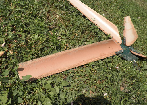
The wind generator seems to be made well, but the propeller is too large diameter, and because of this, the revs are low, and the 1:2 reduction does not really help increase the power of the wind generator. Therefore, charging starts a little late and the speed is low. But I think the creator of this wind generator will understand this in the future. The propeller itself is also made unknown how and has no twist, so most likely it has a low KIEV and speed. Overall the design is good except for the screw.
Wind generator with wheel motor 1 kW
and original fastening
 >
>
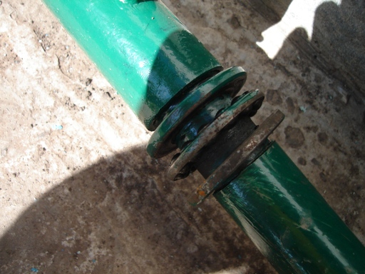
The design of this wind generator, in my opinion, is more thought out. The motor-wheel has a weak axle, the diameter of which is only 12 mm, and besides, it is hollow and wires pass through it. Therefore, if you attach the blades to the body, and the generator by the axis on one side, then this is a very weak fastening and such a thin shaft can easily break. Here an adapter is made with a bearing, which bears the entire load of the screw.
 >
>
The propeller here is three-bladed, has a direct drive to the generator, the propeller itself has a diameter of 2.7-3 meters, and has good speed and KIEV. The power of this windmill with a wind of 4-5 m/s is 150-250 watts, which is already very good.
Wind generators based on wheel motors
Below are links with descriptions to other articles on the site that describe windmills with motor wheels as a generator.  >
>
Wind generator from a 900 watt wheel motor
A bicycle wheel motor is used as a generator in this windmill, the maximum power is fixed at 900 watts, this is 30 volts and 30 amperes, the wind generator runs on a 24 volt battery  >
>
Wind generator from a motor-wheel
Some photos of a small vertical wind generator. The wheel motor from a scooter was used as a generator; torque was transmitted to the generator by a chain, the ratio was approximately 1:2.5. The rotor dimensions are 1*1.6 meters, the mast height is 9 meters. In an average wind, this windmill produces up to 3A and 17v to charge an alkaline battery.In general, the wheel motor is a good generator, but its cost is not that low, it costs about $200-250 per 1 kW, this is its main disadvantage, but it is a godsend for those who cannot make a good generator themselves. Also, as I already wrote, the sticking of the motor wheel is quite noticeable and three-bladed propellers will start poorly in light winds. I myself have not tried to make a windmill using such a generator, but maybe someday it will work out.
Today we will look at very interesting information about how to do homemade wind generator. After all, according to one inventive guy named Ted Baer, it’s very simple. He became the man who made homemade wind generators with his own hands in the form of a whole series of high-power and elementary devices.
A helicopter generator can be considered a more complex alternative to generating electricity using solar panels. Solar panels and possible batteries can provide electricity not only to houses outside the city, but also multi-storey buildings V major cities such as Moscow. read about the types and costs of solar panels and batteries on the Sunways Pv Systems website.
Thus, the blades of our wind design are made of soft aluminum. This material is often used in the manufacture suspended ceilings. Therefore, it can be purchased at any hardware store or even found at home. After all, a good owner will always have the parts necessary for mastery. In order to slightly increase the level of rigidity of our blade, a 40 cm strip can be folded in half and fastened with special rivets.
Next, it’s irresistible to simply take an ordinary unnecessary wheel from a bicycle and begin attaching ready-made blades directly to its spokes. Such a homemade wind generator will be extremely suitable in many cases where it is necessary to generate electricity. But without a generator, of course, these homemade windmills are worth nothing.
Ted recommends using a permanent magnet motor as a generator. In this case, it is important to have a wired belt that would have high level resistance against ultraviolet radiation. Considering the fact that the output current reaches two amperes at a speed of 20 km/h, such a homemade wind generator can really be a worthy competitor solar panels. But subject to constant wind.
According to the calculations of our inventor Ted Baer, such models of homemade wind generators will cost no more than eighty dollars. If you purchase all the parts new at a hardware store. But such simple elements can easily be found at home, as junk in the garage or attic. For example, a bicycle wheel or aluminum plate. Almost every owner has them. Then the cost of such wind generators with your own hands will be significantly reduced, and there will be many benefits. And the work in general is not difficult.
The most expensive purchase here may be a DC generator. It costs around $30 and comes with a special wired strap that can resist UV rays. The latter costs about $10. Although if you are dealing in the agricultural sector, such a belt is used as a drive for a conveyor.
Our DIY wind generators additionally have tail unit. The beam of such a part is made using plastic pvc pipes. It is also worth mentioning that the inventor recommends for his homemade product to use only the rear wheel of a bicycle, which has a diameter of 61 - 69 cm. In this case, the wheel must be attached to the end of the plug plastic pipe. In the middle of which you need to drill a small hole.
We have already mentioned that we use a DC motor as a generator, which has an operating voltage of 24 V. Such a motor was most often used in outdated models personal computers for disk drive. Therefore, you can look for such motor models at a computer junkyard or even in online stores. Maybe they're lying around in a warehouse somewhere? After all, their production has already ceased.
Such wind generators with your own hands must be attached directly to the windmill using a regular corner. Thus, you need to get a fairly strong and reliable shelf. Next, the engine is attached together with the shelf with clamps.
In this case, the pole for strengthening our wind farm is considered at the same time as a trench for electrical wiring. On top of our metal pole, you need to attach a small piece of PVC pipe to contact the plastic with the body of the windmill. In other words, we get a plastic-on-plastic bearing design.
It is also important to pay attention to the fact that the weight of the tail of such homemade wind generators must be selected with the condition of balancing general design windmill Ted Baer approached this issue creatively. After all, to achieve balance, the inventor used one-cent coins.
Wind generator testing
Our inventor carried out his testing of wind generators made with his own hands on his own Windstar minivan, which has a special trunk on the top of the car for attaching a platform. In order to secure such windmill structures with your own hands, it is best to use tripods for mounting a TV antenna on the roof of a house. At the same time, everything technical specifications, for example, wind speed, voltage and current can best be recorded using a video camera. So, for Ted Baer these indicators were as follows - 2A, 16V, 32W at 20 km/h.
Consolidation homemade blades for windmills and their installation
The process of making such a device as wind generators with your own hands is simple. It is important to simply follow all the recommendations, which are outlined in great detail in the articles. So, our blades windmill must be attached by hand to the rear wheel of a bicycle by bending aluminum strips around each individual spoke. In this case, it is best to hook the curved pin into the wound around the next knitting needle. Next, this hook must be inserted into the hole made on each blade.
It is important to understand that the process of bending each blade of our windmill must be done with your own hands. A small piece of metal tinder, for example, 3 mm in diameter, can be a good helper in this case.
Of course, the material that the inventor used is somewhat thinner than what is sold in stores. That is why Ted suggested that the aluminum strip should be doubled. Here you can use different materials to make blades with your own hands. You can, for example. take plastic, wood or plywood. Choose what you already have on hand. In order to somewhat reduce the cost of your invention and make the windmill not only the most useful, but the most profitable.
What characteristics should be taken into account when choosing a location for installing a wind turbine?
It is very important not only to make wind generators with your own hands, but also to place them appropriately. To ensure maximum efficiency of such devices. Such models of homemade wind generators are usually installed on a support, and higher. But it is also important to take into account the characteristics of the area.
For example, do-it-yourself horizontal wind generators are very sensitive to the direction of wind flow. It is recommended to install them so that the wind blows from one side. Whereas the wind generator we made from a bicycle wheel will itself turn in the required direction. And therefore there is no need to place it in any special way. Therefore, horizontal wind generators are not recommended to be installed on the coast of rocks. After all, then, the wind forces created by turbulent flows will not allow the mill to operate efficiently.
When choosing a place to install a DIY wind generator, it is also important to take into account the strength of the wind. Finding such information is not so difficult. After all, via the Internet you can find archived meteorological data for your area. Naturally, they will be somewhat approximate. After all, the nature and strength of the wind will be different in different parts of the city or town. But for general information it will do.
The ideal option for measuring wind force would be special device called an anemometer. After all, it is with its help that you can most accurately measure the strength of the wind flow in a specific place for selection best place installation of a homemade windmill.
Thanks to this article, everyone will have a unique opportunity to make a model of homemade wind generators for minimal cash. And if you try hard, then all the parts and materials can be found from improvised means. The main thing is to understand well the meaning of the idea and realize it somewhat transformed. So to speak, in your own way. After all, all the materials used have analogues that are easy to get or find at home or with friends. Just use your imagination and create something similar with your own hands. What can become a useful device for your comfortable existence and, of course, saving money.
One day I became obsessed with the idea of energy independence and decided to make a windmill. I spent a long time choosing a motor-generator for a windmill. There were several options:
- remake an asynchronous motor by installing permanent neodymium magnets on the rotor
- convert a generator from a car to permanent magnets, thus getting rid of the excitation winding, which needed to be fed well (for comparison: the efficiency of a generator with permanent magnets 0.8, similar to the excitation winding - 0.6).
- Find a ready-made motor with permanent, preferably neodymium, magnets. Why neodymium, you ask, because there are more motors with ferrite magnets. It's simple: almost all motors with ferrite are designed for high speeds, the minimum I found was 1500 rpm, 36 volts. This means that the design of the wind generator is complicated by a gearbox, which will reduce the overall efficiency of the entire product and complicate the design, as well as operating costs, in short, a complete mess.
- Wooden blades are not bad, but labor-intensive to manufacture and require maintenance (painting, varnishing)
- Blades from composite materials(fiberglass and epoxy) - labor-intensive production
- PVC pipe blades - easy to manufacture and require no maintenance
The length of the blade from the pipe is approximately calculated as follows: blade length = pipe diameter * 5. You can, of course, make them longer, but they will bend very strongly in a strong wind. Divide the diameter of the pipe into 4 equal parts, then cut along the length of the pipe, and you will get 4 blanks. Then mark 30-35 mm from one edge and draw a line to the corner of the other edge of the workpiece, cut off the excess. All the blades are ready, we do the same operations with the rest, and you get 4 beautiful blades. Next, we grind the corners for better aerodynamics. 
Manufacturing of blade mounting unit (Hub)
I made it from a plate 1.5-2mm thick. Cut out a circle and mark it into 5 equal parts. We drill holes for the bolts that will attach the blades and the hub to the motor wheel. 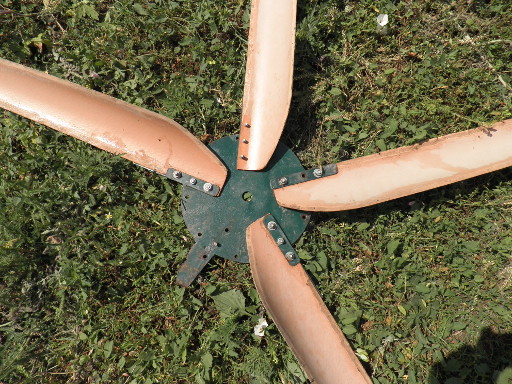
Rotary mechanism and fastenings for MK 


Hello. Probably every do-it-yourselfer has a desire to try himself in alternative energy, and this desire awoke in me. In fact, many years ago I dreamed of building my own wind generator, but there was no money or time. But recently I was browsing through Youtobe and saw a homemade wind generator from a hoverboard wheel motor assembled by my fellow countryman (I’ll add a video at the end of the article). Magnetic wheel motor ideal option for building low-power generators, I thought, and began to look for my options
New motor wheels are very expensive, but used wheels cost almost nothing. I went to Avito and found two wheels. I bought one 6.5 inches for 800 rubles along with delivery by Russian Post from Evpatoria, and the second 10 inches was given to me for experiments by Nikolai from the Krasnodar Territory, for which I am most grateful to him.
The first one that came to me was a 10-inch wheel motor with a power of 350W. The wheel is no longer suitable for a hoverboard, since some white dust inside the rim has eaten the aluminum to holes in two places, but it’s just right for a wind generator. This is a ten inch wheel

Under the cover is a stator with 27 windings and 30 poles on neodymium magnets, the cover is secured with 6 M6 bolts 
It's time to move on to the base of the windmill. A square was welded from a corner 40*40*3. On the front side, another piece of angle with a slot for the wheel motor shaft was attached to the top. 10.5 mm holes were drilled in the frame and this corner for M10 bolts 
Thus the motor wheel was jammed. I tried to turn the wheel to the side, but nothing happened.
The motor wheel is secured very securely. Naturally, under the M10 nuts there are groovers 
The base of the frame is ready and we need to think about the tail with protection from side gusts. A meter-long pipe was taken, cut lengthwise in the tail section to attach the tail blade, and a U-shaped part made of a 4 mm strip of metal was welded vertically on the front side 
Now a long tube matched to the U-shaped part is vertically welded to the main frame from the tail side in the middle. The frame is connected to the tail with a metal pin 
Next, I welded a Y-shaped part to the frame, on the edge of which I drilled a hole for the spring. I welded an M6 bolt onto the tail pipe to secure the same spring. This spring is needed to fold the tail during a strong gust of side wind; in this way, the windmill turns smoothly with the wind and the load on the mast is much less. And there is less load on the blades themselves 
A little more detail on where the tail and main frame are attached 
In principle, the frame is ready and I’ll move on to the blades and their attachment to the motor wheel from the hoverboard. The mounting adapter was cut from 0.8mm sheet metal. For accurate markings I had to remember the basics of geometry. On piece of paper A4, I drew a circle with a compass, inscribed an equilateral triangle in it, and drew rays through the center of the circle and the vertices of the triangle. The end result is this detail. The drawing on the workpiece is incorrect, so please ignore it. 
Now it's time to make the blades. A piece was cut out 160 piece sewer pipe, three parallel lines are drawn. It is good to draw the first line along the pipe marking, and then divide it into three equal parts and draw two more lines. I used the pattern from ready-made calculations from the E-Veterok website
To view click on the picture 
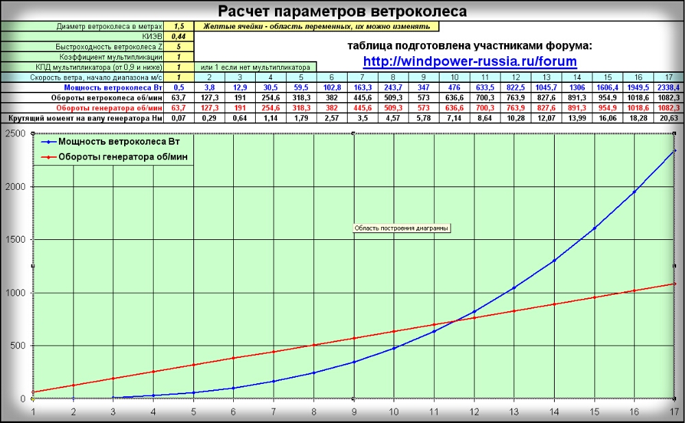
Here is a pattern for a 5 meter wind at 318 rpm, it is at these rpms that battery charging begins, according to calculations

I glued the pattern to the pipe and transferred the drawing 
Next, I cut out the blades with a grinder 
It was not possible to check the alignment at the table in the garage due to lack of space. To check the alignment, I drove a meter-long pin into the ground and secured the entire structure 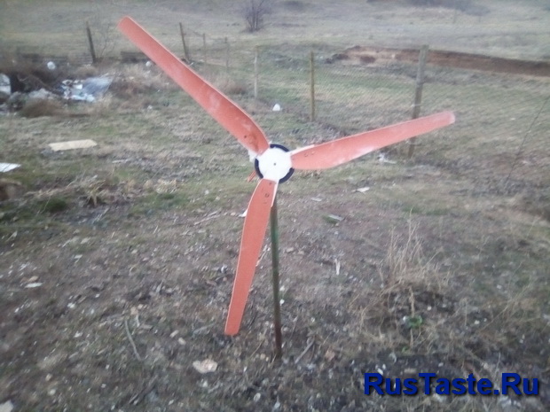
Surprisingly, the design turned out to be very balanced. Next, I came up with a rotating mechanism from an old Ganov generator and installed everything on a four-meter mast and got so carried away with my work I forgot to take a picture of what and how, but it’s not scary because everything had to be redone.
Firstly, 0.8 mm of metal was not enough even for a 5 m/s wind and the blades bent already on the second day, and the tail was very heavy and outweighed the entire structure, which made it difficult for the windmill to turn with the wind. Eh, sorting it all out again, but oh well
As I said, I used a lawn generator for the turning mechanism. I installed a 40A diode bridge under the cover and insulated it well from the frame using heat-shrinkable tubing and PCB plates. So the voltage will come through two wires, already rectified  The rotor crowns were cut off from the shaft, the winding and the iron blank were removed. The teeth themselves on which the rotor rested were ground down so that the bearing could be placed lower. Only the slip rings remain. Instead of the original M4 bolts, holes were drilled for M6 and in places where the bolt would not fit, the edge was ground off with a grinder, sometimes to the point of holes


I will relieve the voltage through current collection brushes 
As I said, the 0.8mm thick adapter couldn’t cope and I had to cut the same one and put them together. The adapter is attached to the wheel along the side with M4 bolts at 9 points, three per side. Three bolts from them re-attach the blade. The blades are screwed to the adapter with M6 bolts, three per blade, plus M4 through the side of the wheel 


On the front side I reinforced the fastening with a strip of 3 mm metal 
The front cover of the generator was screwed to the frame from below. Longitudinal grooves were machined into the shaft for pulling cables.


And this is what everything looks like inside 
General view of the windmill. As you can see from the results, I shortened the tail by half, and increased the tail blade by one and a half times, and the windmill is normally balanced 

Well, now everything is painted and a casing made of galvanized sheet is installed on the windmill 
I lifted everything onto a 4 meter mast. The display shows almost 28V at idle at 5m/s 
The display shows 42V at idle at 5m/s with a small gust 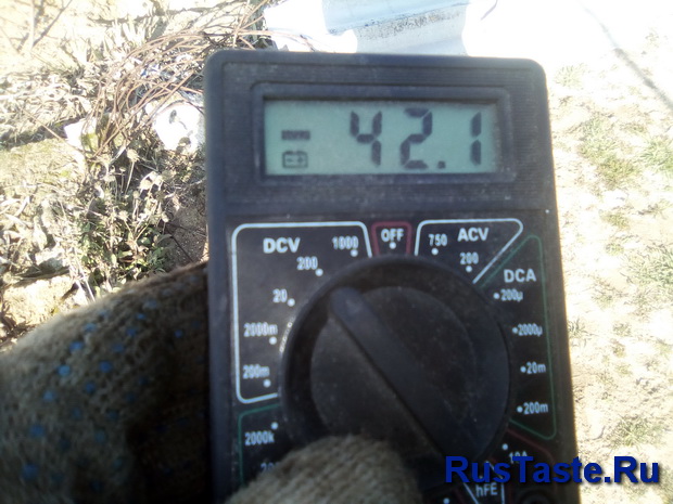
And this is what it looks like on a temporary mast 
While the windmill is not in use, the wires are short-circuited. This type of brake, speed in a wind of 5 m/s is about 40 per minute. It is necessary to assemble a controller that will limit the voltage to 14.4V to charge the battery, but there are no powerful field-effect transistors. I have already ordered transistors from China and in about 3-4 weeks I will be connecting everything and recording what this little windmill can do from the motor of a hoverboard wheel. To find out what happens next, subscribe to updates on

If you are concerned about the issue of obtaining alternative energy, you can assemble for yourself such a simple wind generator. The main part of the spare parts used are bicycle parts. With the help of sprockets and a chain, torque is transmitted to the generator. A part from a bicycle also acts as a generator - it is a dynamo. If you don't have a dynamo, you can use a DC motor.
Regarding propeller, then it is done very simply and also from available materials. At the moment the easiest way to make a screw is from PVC pipe or similar material, the pipe has suitable profile for the manufacture of blades.
You will also need to find some scrap metal to make a mast, make a base, and so on. Let's look at this topic in more detail.
Materials and tools that the author used to make the windmill:
Materials:
- a piece of PVC pipe;
- metal plates;
- thin galvanized sheet steel;
- nuts, bolts;
- bearings;
- a piece of metal tube (for making bearing housings);
- metal clamps (3 pieces);
- paper, marker, scissors (for making a template);
- glue;
- steel corner;
- pipe square section(mast);
- a wheel from a trolley;
- dynamo (or DC motor);
- driving and driven sprocket, chain (from the bicycle).
Tools:
- scissors;
-
- screwdriver;
- pliers;
-
- multimeter;
- wrenches and other little things.
Windmill manufacturing process:
Step one. Let's start with the blades
The author makes the blades from a piece of PVC pipe. The first step is to make a template out of paper and then cut it out with scissors. We attach the template to the pipe and cut out the blades. Each new blade is cut out one by one, resulting in little waste. It is convenient to cut a pipe using.


Mark the beginning of each blade and cut out the pieces as the author did. The remaining parts are needed to attach the blades to the axle. Metal plates with holes are used as fasteners. We apply the plate to the blade and mark the places for drilling holes. In total, the author drills three holes in each blade.


As for the plates, cut them so that there is a free end left for attaching it to the central disk. Finally, trim all the blades with a grinder so that they do not have nicks and so on.


Step two. Making the screw core
The core of the propeller, to which the blades are screwed, is made of three plates, a round piece of sheet steel, and a nut. Mark on the central disk where the blades will be located, and also determine the center. We install a nut in the center; the author glues it with superglue for ease of assembly.


Let's start welding. First of all, weld the nut that we glued earlier. You need to weld it well, as it the only place where the propeller will be mounted. Then weld the plates to the disk to which the blades are attached. They also need to be welded carefully; the author makes a weld on both sides.


Step three. Screw assembly
Assemble the propeller. To do this, you simply need to screw the blades to the core using bolts and nuts.


Step four. Making the base
So that the windmill does not fall and can be secured, make it solid foundation. To do this, the author cuts a metal corner and then welds the frame.


Step five. Prepare the bearing
In order for the windmill to rotate in any direction around its axis, you will need to secure it to a bearing. Such a bearing is a wheel from a trolley, which can rotate 360 degrees. Cut off the excess from it with a grinder.


Step six. Assembling the windmill frame
The windmill mast is made from a piece steel pipe, the author has it with a square section. The height of the pipe is not large; this design rather implies installation on the roof or on another hill. Weld the mast to the base made earlier.


Weld the part that we extracted from the cart wheel to the upper end of the mast. Then a steel plate in the shape of the letter “L” is welded to it; it will be needed to attach the tail.


Step seven. Bushing with bearings
The propeller shaft rotates on two bearings. The author pressed these bearings into a piece metal pipe. Be sure to lubricate the bearings well before installation. In order not to be tricky with the bushing, you can also successfully use a ready-made bushing from the front or rear axle of bicycle wheels.


Step eight. Mounting clamps
The author secures the generator and bushing with bearings using ordinary steel clamps. To secure the dynamo to the machine, you will need to weld an additional plate to the frame.


Step nine. Tail fasteners
Find metal plates and weld them as seen in the photo. One part is welded directly to the rotating plate of the windmill.


Step ten. Sprockets and chain
Take the front bicycle sprocket and cut off any excess from it. Weld a nut to the center. This sprocket is located on the propeller shaft.
Install the dynamo into the clamp and install a small diameter sprocket onto the shaft. This will allow you to get fairly high generator speeds at relatively low propeller speeds. That's it, cut to required sizes and put on the chain.