Today you can download free drawings of a paper model of the T-34 tank at the end of our article.
The main difference between these tank drawings is the prefabricated tracks. Since they are made from individual links, you can give the paper model tank tracks any shape. This paper model can be placed on a diorama or in a closet.
To assemble a paper model of a tank, you only need a paper cutter, paper and glue. Well, also a color printer for printing drawings of a paper model. Assembly of this paper model is quite simple, it just requires care when assembling small parts.
The T-34 tank played a decisive role in all major battles of the Red Army during the Great Patriotic War. Patriotic War. Universal in its essence, it was successfully used both for direct support of infantry and for high-speed maneuverable combat operations.
During the Great Patriotic War, the T-34 became the basis of the Red Army tank fleet. The country's seven largest factories produced over 54,000 T-34 tanks - more than 70% of all types of tanks produced. The T-34 tank turned out to be best suited for mass production, it was quite simple to manufacture, operate and repair, and had a relatively low cost. Important Feature"Thirty-four" - ease of mastering of a combat vehicle by its crew.
Nowadays, T-34 tanks stand on pedestals in cities and villages in many countries around the world and adorn the collections of the most prestigious military-historical and technical museums.
By the way, there is a very interesting film on plasticine animation about the Soviet T-34 tank.
This film about the T-34 tank tells the whole history of design modernization in an ironic form. I recommend watching!
Download free drawings of a paper model of the T-34 tank Can
Description of the presentation by individual slides:
1 slide
Slide description:
Municipal budgetary educational institution "Verkhovskaya secondary school No. 1" Museum model of the T-34 tank Completed by: 11th grade student Alexander Shakhov Supervisor: technology teacher Oleg Ivanovich Martynov VERKHOVYE 2014
2 slide
3 slide
Slide description:
SELECTION AND JUSTIFICATION OF THE TOPIC OF THE PROJECT I am in the 11th grade, at the school museum of local history I am involved in the “Local History” club, I also like to make crafts, I am interested in technology. Our museum has a Hall of Military Glory. It contains documents telling about the battles for the liberation of our village from the Nazis, and there are some samples of weapons of the Red Army and Nazi Germany. There are models - copies of the main combat aircraft, made by members of the aircraft modeling circle. Last year I also made a model of the LA-5 fighter plane and donated it to the museum. In 2015, our country celebrates the 70th anniversary of Victory in the Great Patriotic War. In this regard, and after consulting with the head of the museum, I decided that the theme for my project would be to make a model copy of some type of armored vehicle and add it to the museum’s exhibition. 1
4 slide
Slide description:
GOALS AND OBJECTIVES Goal: To create an original product useful for school. Objectives: 1.Know and perform modeling techniques. 2. Learn to mentally imagine an object and graphically express it in the form of a technical drawing and drawing. 3.Work with technological documentation. 4.Know and correctly perform operating techniques on machines. 5. Express your opinion in a reasoned manner and accept the right decision when designing. 6. Really evaluate your knowledge and skills. 2
5 slide
Slide description:
SELECTION OF PRODUCT OPTIONS Having considered several types of tanks that were in service with the Red Army during WWII, I chose the legendary thirty-four tank, the T-34 tank. In my opinion, it looks very nice and will be easier to make than the others. 3
6 slide
Slide description:
7 slide
Slide description:
The “biography” of the thirty-four began in October 1937, when the tank design bureau of the Kharkov plant received an order from the Main Automotive Armored Directorate of the Red Army to design new car, capable in the future of replacing the BT type tank that was in service. Work has begun on creating a tank with projectile-proof armor. Wheel design – tracked vehicle with 30 mm armor and a 45 mm gun was carried out at the Kharkov plant in the design department headed by M. Koshkin. A year and a half later, the USSR Defense Committee was presented with a project for a tracked tank, named A-32. On December 19, 1939, the government of the country decided to create an improved version of the A-32 tank - the T-34 medium tank, which later became one of the most famous in the history of world tank building. Production of the first two experimental thirty-fours began in January 1940. And already at the end of February the tanks set off under their own power for Moscow. After the vehicles were shown in the Kremlin, field tests began. The T-34 was forced to overcome the most difficult obstacles and perform dizzying maneuvers. They were fired at directly with high-explosive and armor-piercing shells. In June 1940, the Politburo of the Central Committee of the All-Union Communist Party of Bolsheviks decided to launch production of T-34 tanks. By January 1, 1941, the Kharkov plant managed to produce 115 of the 600 ordered vehicles. 5
8 slide
Slide description:
In the spring of 1941, designers and technologists began a tremendous effort to improve and simplify the production of thirty-fours. First of all, this concerned the manufacture of towers. In the first vehicles they were welded from rolled armor plates. This process was complex, time-consuming and expensive. In an effort to simplify it, engineers developed new technology, which involved welding a turret with an armor thickness of 52mm from just two cast elements. By the beginning of the Great Patriotic War, the Red Army already had 1,225 T-34 tanks, of which western districts-967. The Stalingrad Tractor Plant and the Krasnoye Sormovo plant in Gorky joined production. Both opponents and our allies in the Second World War failed to create a tank superior to the legendary thirty-four. The T-34 was reliable, easy to manufacture, operate and repair, and easy to train. Thirty-fours bore the brunt of the fight against the fascist armored hordes from 1941 to 1945. 6
Slide 9
Slide description:
10 slide
Slide description:
DRAWINGS OF THE T-34 -76 TANK I found the drawings of the tank in the “Model Designer” magazines. Using an epidiascope, I enlarged them to the scale I needed, 1:10, then, using them, I developed and cut out of cardboard the hull, turret, and fuel tanks, and made technological maps for manufacturing the main parts of the tank. 8
11 slide
Slide description:
12 slide
Slide description:
SELECTION OF MATERIALS To make my product, I used available and cheap construction materials: wood and metals. For the body I chose galvanized sheet metal, 0.2 mm thick. It bends, solders, and processes well. The metal body allows you to attach and perform the smallest parts on it with great reliability using the method of soldering and surfacing of tin with further processing. The tank turret, road wheels and final drive housings are made of birch wood. Birch has white wood with a brownish tint, hard, dense. Well processed and sharpened. Steel St-3 is a cheap, accessible structural material. Durable, well processed, sharpened, soldered. The gun barrel, front guides and rear drive wheels are machined from a steel bar. Copper is a soft metal with an orange-red color. Easily processed, bent, soldered. Copper tubes and wire were used to make exhaust pipes, machine guns, and staples. Tin is a soft, heavy metal, silvery in color, does not oxidize, and melts easily. Used as solder and for casting track tracks. 10
Slide 13
Slide description:
Epoxy universal adhesive. Used for gluing metals, their alloys, glass, wood. Primer GF – 021. Used to coat the product after assembly before painting. Alkyd enamels PF-115 various colors. Soldering acid is a flux for soldering metals. 11
Slide 14
Slide description:
SELECTION OF TOOLS AND EQUIPMENT 1. Lathe TV-6 2. Lathe STD-120 3. Drilling machine 4.Drill 5.Set of files 6.Set of files 7.Set of drills 8.Zhezhevka 9.Jigsaw 10.Plane 11.Ruler 12.Scratcher 13.Puncher 14.Calipers 15.Compass 16.Pencil 17.Awl 18.Knife 19. Hammer 20. Set of brushes 21. Sandpaper 22. Soldering iron 23. Compressor 24. Paint gun 12
15 slide
Slide description:
TECHNOLOGICAL CARDS Based on the drawings, with the help of a technology teacher, I developed and compiled technological maps for the manufacture of the main parts and components of the T-34 -75 tank. 13
16 slide
Slide description:
MANUFACTURING THE UPPER PART OF THE TANK HULL No. Name Quantity Scale Material 1 Upper part housing 1 1:10 Tin Technological map № 1 14
Slide 17
Slide description:
Sequence of technological operations Graphic representation Tools Equipment materials 1. Cut the workpiece required sizes Ruler Scriber Metal scissors Tin 2. Apply the contours of the part to the workpiece Template Scriber Punch 3. Cut out the development of the part. Metal shears File Remove burrs 4. Drill marked holes Drill sled Hand vice Drill 5. Bend the reamer along the fold lines. Solder the corners. Metal shears Bench vice Mandrel Soldering iron 15
18 slide
Slide description:
Slide 19
Slide description:
Sequence of technological operations Graphic representation Tools equipment materials 1. Select a workpiece of the required size Ruler Pencil Hacksaw Wood 2. Mark the contours of the bottom of the tower using a template Pencil Template 3. Mark the contours of the top of the tower using a template Pencil Template 4. Drill a hole to install the barrel of a gun Bench vice Drill Drill 5. Process the part according to the markings. Clean surfaces. Planer Rasp Emery cloth 17
20 slide
Slide description:
MANUFACTURING THE SIDE WALL OF THE LOWER PART OF THE TANK HULL No. Name Quantity Scale Material 1 Side wall 2 1: 10 Tinplate Technological map No. 3 18
21 slides
Slide description:
Sequence of technological operations Graphic representation Tools Equipment Materials 1. Cut out the workpiece of the required size. Ruler Scribbler Metal scissors Tin 2. Draw the contours of the part according to the template. Template Scriber Punch 3. Cut out the part. Remove burrs. Metal shears File 4.Drill holes Drilling machine Hand vice Drill 19
22 slide
Slide description:
Manufacturing of the engine cover No. Name Quantity Scale Material 1 Engine cover 1 1:10 Tinplate Technological map No. 4 20
Slide 23
Slide description:
Sequence of technological operations Graphic representation Tools Equipment Materials 1. Cut out the workpiece of the required dimensions Ruler Pencil Metal scissors Tin 2. Apply the contours of the part according to the template Template Scratch punch 3. Cut out the part. Remove burrs. Metal scissors File 4. Drill the marked holes. Drilling machine Hand vice Drill 5. Cut out the engine ventilation windows. Remove burrs. Hammer Chisel File 21
24 slide
Slide description:
Sequence of technological operations Graphic representation Tools Equipment Materials 6. Bend the part along the fold lines. Bench vice Mandrel Hammer Pliers 7. Solder the corners 8. Close the engine ventilation windows with a mesh Soldering iron Soldering acid Solder Soldering iron Soldering acid Solder Metal mesh 9. Perform final cleaning of the part File Emery cloth 22
25 slide
Slide description:
MANUFACTURING A GUN MUZZLE No. Name Quantity Scale material 1 Gun barrel 1 1: 10 Steel Technological map No. 5 23
26 slide
Slide description:
Sequence of technological operations Graphic representation Tools Equipment Materials 1. Select a steel bar of the required size. Ruler Hacksaw for metal Rod Bench vice 2. Secure the workpiece in the chuck of the lathe. Drill a hole. TV-6 lathe Drill 3. Secure the workpiece in the lathe chuck and the tailstock cone. TV-6 lathe Workpiece 4. Turn the workpiece to the required size. Lathe TV-6 Cutter Vernier calipers 5. Perform final cleaning of the part. Sanding device Sandpaper 24
Slide 27
Slide description:
Manufacturing of the fuel tank No. Name Quantity scale Material 1 Fuel tank 3 1: 10 Tinplate Technological map No. 6 25
28 slide
Slide description:
Sequence of technological operations Graphic representation Tools Equipment Accessories 1. Cut out the workpiece of the required size. Ruler Scribbler Metal scissors Tin 2. Draw the contours of the part according to the template. Sketcher template 3.Cut out the pattern of the part. Remove burrs. Metal scissors File 4. Bend the workpiece along the fold lines. Pliers Workpiece 5. Solder the seams of the workpiece. Soldering iron Soldering acid Solder 26
Slide 29
Slide description:
MANUFACTURE OF BACK ROLLER No. Name Quantity Scale Material 1 Support roller 10 1: 10 Birch Technological map No. 7 27
30 slide
Slide description:
Sequence of technological operations Graphic representation Tools Equipment Materials 1. Select a workpiece of the required dimensions Ruler Pencil Hacksaw Wood 2. Mark centers at the ends of the workpiece. Plane the edges. Carpentry workbench Planer Ruler Pencil 3. Mark and make a cut at the end of the workpiece. Mark the centers. Ruler Pencil Hacksaw Punch Hammer 4.Secure the workpiece in the lathe. Process to the desired diameter. Lathe STD-120 Chisels Vernier calipers 5. Grind tenons and chamfers. Clean surfaces. Cut off the part. Lathe STD-120 Chisels Emery cloth 28
31 slides
Slide description:
Sequence of technological operations Graphic representation Tools Equipment Materials 6. Secure the workpiece in the chuck with reverse jaws. Lathe TV-6 Workpiece 7.Drill a hole. Lathe TV-6 Drill 8. Make grooves on the ends of the workpiece. TV-6 lathe Cutter Vernier calipers 9. Perform final cleaning of the part TV-6 lathe Emery cloth 29
32 slide
Slide description:
MANUFACTURING GUIDE WHEEL No. Name Quantity Scale Material 1 Guide wheel 2 1: 10 Steel Technological map No. 8 30
Slide 33
Slide description:
Sequence of technological operations Graphic representation Tools Equipment Materials 1. Select a workpiece of the required size. Ruler Vernier calipers Hacksaw for metal Steel rod 2. Secure the workpiece in the lathe chuck and grind to the required diameter. Lathe TV-6 Cutter Vernier calipers 3. Grind a tenon in the workpiece to the required depth. Lathe TV-6 Cutter Vernier calipers 4. Make a groove from the end of the workpiece. Lathe TV-6 Cutter Vernier calipers 5.Drill a hole in the workpiece. Lathe TV-6 Drill Caliper 31
Slide 34
Slide description:
Sequence of technological operations Graphic representation Tools Equipment Materials 6. Cut off the finished part. Lathe TV-6 Cutter Vernier calipers 7. Make a groove at the end of the part. Lathe TV-6 Cutter Vernier calipers 8. Mark and drill holes. Caliper Punch Hammer Drilling machine Drill Vise 32
35 slide
Slide description:
36 slide
Slide description:
Safety precautions when working on a TV-6 screw-cutting lathe Before starting work: Put on work clothes, fasten your sleeves, prepare safety glasses. Firmly secure the cutter and the workpiece. Remove the cartridge key. Check the handles of the machine, move the cutter away from the workpiece. Turn on the machine and check its operation for idling. During operation: Smoothly move the cutter towards the workpiece. It is prohibited: - to measure the workpiece being processed; -remove chips, lubricate and clean the machine without turning it off; - move away from the working machine; -after turning off the machine, brake the chuck by hand; -transmit and receive objects through rotating parts of the machine; - blow off and sweep away the shavings by hand; Upon completion of work: Move the support away from the chuck and turn off the machine. Put the machine in order, workplace, tools, equipment. Place waste in a special box. 34
Slide 37
Slide description:
SAFETY INSTRUCTIONS WHEN WORKING ON A DRILLING MACHINE Dangers at work: 1. Eye injury from flying chips. 2. Injury to the hands due to poor fastening of the part. Before starting work: 1. Put on proper clothing. 2.Check the reliability of fastening protective casing belt drive, connection of protective grounding to the machine body. 3.Check the operation of the machine at idle speed. 4. Securely secure the drill in the chuck. 5.Fix the part firmly on the machine table. 6. Wear safety glasses. During operation: 1. Feed the drill to the part smoothly, without effort or jerking. 2.Before drilling a metal workpiece, mark the centers of the holes. 3.When the drill comes out of metal, reduce the feed. 4.Do not slow down the chuck and drill with your hands. 5.Do not leave the machine without turning it off. Upon completion of work: 1. Remove chips from the machine using a brush and hook. 2.Do not blow away the shavings with your mouth or sweep them with your hands. 35
Slide 38
Slide description:
SAFETY TECHNIQUES WHEN MANUAL PROCESSING OF METAL Dangers in work: 1. Injury from metal fragments. 2. Injury when working with a faulty tool. 3. Cuts with burrs. Before starting work: 1. Put on proper clothing. 2. Wear goggles when chopping metal. 3.Check the condition of the tools. 4.Check the condition of the bench vice. During operation: 1. Firmly secure the workpiece in a vice. 2.Do not check the quality of the sawn surface with your fingers. 3.Use the plumbing tool only for its intended purpose. 4. Hold the sheet metal workpiece being cut when cutting with scissors in a glove (mitten). After finishing work: 1. Clean the work area thoroughly (do not blow away shavings or sawdust or brush them away with your hands). Place waste in a special box. 2.Put the tools in their places. 3.Get yourself in order. 36
Slide 39
Slide description:
RULES FOR SAFE WORK WHEN SOLDERING METALS 1. During work, use ventilation to remove dust and harmful vapors. 2.Use a working soldering iron with a dry handle and carefully insulated wires. 3.Handle hot soldering iron, melted solder and hot parts with care. 4.Install the soldering iron on a special stand. 5. Place a rubber mat under your feet. 6. Handle fluxes carefully, do not allow them to splash or get on your body. 7. Keep fluxes in special containers on stands. 8.After finishing work, wash your hands with soap and water. 37
40 slide
Slide description:
RULES FOR SAFE WORK WITH A MUFFLE FURNACE 1. Check that the protective grounding is securely attached to the furnace body. 2.Open and close the oven door only after disconnecting it from the power supply. 3.Do not place flammable objects on or near the stove. 4. Place the container with materials in the oven and remove it from it using pliers with long handles. 5.Handle molten metal carefully. 6.When working with metal, wear a canvas apron. 7.Wear gloves and safety glasses. 8.After finishing work, turn off the oven. 38
41 slides
Slide description:
SAFETY INSTRUCTIONS WHEN WORKING WITH ADHESIVES AND PAINTS When working with paint and varnish materials, adhesives, putties, the workplace must be equipped with ventilation, well lit, and free of dust. Observe the following rules: - protect hands and clothing from contact with paints, enamels, glue - use a respirator - use rubber gloves - ensure proper ventilation - after finishing work, wash your hands thoroughly with soap 39
42 slide
Slide description:
43 slide
Slide description:
44 slide
Slide description:
45 slide
Slide description:
46 slide
Slide description:
Slide 47
Paper model of the T-34 tank model 1940 and 1942(colloquially “thirty-four”) - a Soviet medium tank during the Great Patriotic War, mass-produced since 1940, was the main tank of the Red Army until the first half of 1944, when it was replaced by the T-34-85 modification tank. The most popular medium tank of World War II.
Materials and tools:
- scissors, paper knife, drawing ruler;
- tweezers;
- brushes for glue and paint;
- watercolor paints (or pencils), toothpicks;
- transparent acrylic glue(“Moment”, etc.);
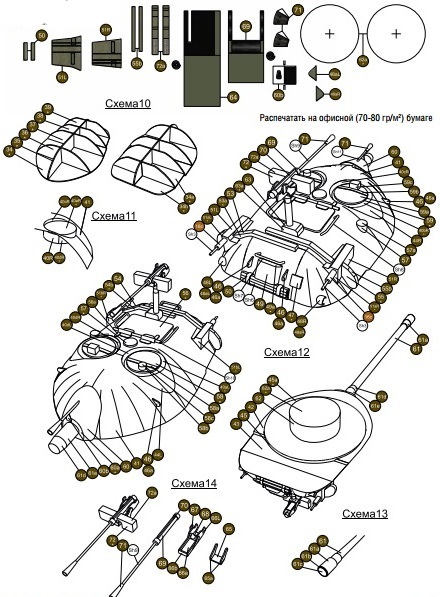
- for printing the model, matte photo paper with a density of 170-180 g/m2; for small parts - 70-80 g/m2.
- Before assembling the part, read the drawings and instructions. Determine the location of each part and imagine its assembly;
- make holes in the parts before cutting out the part itself;
- cut only the part(s) you need right now. Place unfinished parts in a box, and unused sheets in a closed folder (optional). When throwing away trash after work, carefully inspect the paper scraps;
- For better bending of the part, it is necessary to draw it along the fold line under the ruler, pressing lightly, with the blunt side of a knife or a toothpick so as not to damage the surface of the paper. It is better to do this from the wrong side of the part;
- keep your fingers clean and be sure to use napkins to wipe your hands, because your hands may get dirty during work;
- Before gluing, wrap cylindrical parts around a round object of suitable diameter, this will give them shape;
- Before gluing it is necessary to paint over the ends of the part. White trim lines spoil general view models. To paint the ends, use watercolor or gouache paints. Having chosen the desired color, apply them thin layer, then give the paint time to dry. It’s better to forget about felt-tip pens;
- take your time with gluing. First, cut out the part, paint it from the end, wait for the paint to dry, and assemble the part. Place it where it needs to be to make sure everything is done correctly. And only then glue it. Don't forget to let the glue dry.
A little history
Soviet medium tank T-34 mod. 1940 and 1942


T-34 tank (photo)T-34 tank (photo)T-34 tank (photo)_1T-34 tank (photo)_1
On October 13, 1937, ABTU issued the plant technical requirements for the design of a new combat vehicle - the BT-20 wheeled-tracked tank. Two weeks later, the director of plant No. 183, Yu.E. Maksarev, received an order from the Main Directorate, which included the words: “By Government Decision No. 94ss of August 15, 1937, the Main Directorate was asked to design and manufacture prototypes and prepare production for serial production by 1939 high-speed wheeled-tracked tanks with synchronized movement."
To develop a new tank, ABTU sent captain E.A. Kulchitsky, military engineer 3rd rank A.Ya. Dik, engineers P.P. Vasiliev, V.G. Matyukhin, Vodopyanov, as well as 41 VAMM graduate students to Kharkov. In turn, the plant contributed several of its designers, including A.A. Morozov. A.Ya. Dik was appointed head of the design bureau, engineer P.N. Goryun was appointed assistant head, and E.A. Kulchitsky was appointed ABTU consultant. Information about the activities of this group that has so far been discovered ends at the beginning of November 1937. However, it is reliably known that the technical specifications for the BT-20 tank (factory index - A-20) were largely based on the developments of A.Ya. Dick, made in the summer of 1937.
The technical design of the tracked tank, designated A-32, was completed quickly, since outwardly it was no different from the A-20, with the exception of the chassis, which had 5 (not 4, like the A-20) road wheels per side. In August 1938, both projects were presented at a meeting of the Main Military Council of the Red Army under the People's Commissariat of Defense. The general opinion of the participants was again inclined in favor of the wheeled-tracked tank. And again Stalin’s position played a decisive role: he proposed to build and test both tanks and only after that make a final decision.
On September 23, 1939, a demonstration of tank equipment to the leadership of the Red Army took place, which was attended by K.E. Voroshilov, A.A. Zhdanov, A.I. Mikoyan, N.A. Voznesensky, D.G. Pavlov and others, as well as the main designers of the tanks being presented. In addition to the A-20 and A-32, heavy tanks KB, CM K and T-100, as well as light BT-7M and T-26 tanks were delivered to the training ground near Moscow.
The A-32 “performed” very impressively. Easily, even gracefully and at a good pace, the tank crossed a ditch, a scarp, a counter-scarp, a spear bridge, forded the river, climbed a slope with a rise of more than 30° and finally knocked down a large pine tree with the bow of the armored hull, causing the admiration of the spectators.
Based on the results of tests and demonstrations, the opinion was expressed that the A-32 tank, which had a reserve for increasing mass, would be advisable to protect with more powerful 45-mm armor, correspondingly increasing the strength of individual parts.
In an extremely short time, the design bureau carried out modifications to the T-32 tank by further enhancing armor protection, armament and implementing a number of other design changes. As a result of this work, a sample tank was created, which was named T-34 and later became the main tank. Soviet Army during the Great Patriotic War. The chief designer of the joint design bureau developing the T-34 was M.I. Koshkin, head of the design bureau and deputy chief designer - A.A. Morozov, deputy head of the design bureau - N.A. Kucherenko.
The T-34 tank was adopted by government decree on December 19, 1939, before the production of prototypes. The first experimental tanks were manufactured in January 1940 and during testing they fully confirmed their high technical and combat qualities. In March 1940, two T-34 tanks made a run to Moscow and back, demonstrating high reliability of all components. M.I. took a direct part in this run. Koshkin. In June 1940, the government decided to expand the production of T-34 tanks at other large enterprises in the country. In connection with this, the design bureau of plant No. 183 was in urgently complete sets of drawing and technical documentation for the T-34 tank were produced and required quantities sent to the Stalingrad Tractor and Sormovo Shipbuilding Plants.
Creating paper tanks can be of interest not only to boys, but also to girls. Firstly, these figures will be excellent toys for them. Secondly, the process of creating a figure itself arouses unprecedented interest in children and develops motor skills. And thirdly, during the process of forming such figures, many parents tell their children about the great wars and their features, attracting children to the history of their state. So, how to make a tank out of paper and where to find a layout and drawing?
Creating paper tanks can interest not only boys, but also girls
A T 34 tank made of paper corresponding to a real vehicle can be glued together using ready-made developments. To do this, you will first need to print on thick paper the necessary sweep. Then you should cut out all the drawn parts.

 To make T 34 from a reamer, you must follow the instructions:
- Fold lines should be found on the cut out elements. A ruler is applied to each of them, and then the free edge of the paper is lifted and ironed. This creates an even fold.
- Once all the folds have been marked, you can proceed to gluing the model.
- The first step is to glue the main body of the tank. To do this, it is advisable to use transparent acrylic glue or quick-drying PVA.
- Then all minor parts are glued to the body.
- Then you can move on to the cannon. First of all, its base is glued together, and only after that the cannon is supplemented with secondary elements. Finished model glued to the main body of the combat vehicle.
- After this, the caterpillars are assembled. First, the inner circles are made, and only after that they are framed by a single track strip. The finished tracks are attached to the sides of the hull.


It is worth considering that there are different layouts of the T 34 tank, which may differ from each other color scheme and convention. If you can only print a black and white version of the machine, you should color it using acrylic paints. Such processing of cardboard will allow the future toy to acquire the appearance of a tank with a natural coating.
Gallery: paper tank (25 photos)


Tank IS 7 made of paper
To make this tank, you should also use a ready-made reamer.


- All elements of the development are cut out using a stationery knife.
- Next, using a ruler, folds are made at all places marked for these purposes.
- In production supporting structure for the body. It is made from two rectangles installed parallel to each other and secured with 3 transverse strips located at an equal distance from each other.
- A body with a circle cut out in it is glued to the resulting base.
- The sides of the body are pasted over, niches for the caterpillar are formed. A tank bottom is being formed.
- The base for the cannon mount is being made. It's being done in the same way, as for the body. A manufactured turret is installed on the hull. A machine gun and additional elements are glued to the turret.
- Next, the tracks are made: the middle ones are smooth, the rear ones are with teeth.
- The tracks are glued to the bottom of the main body and secured with caterpillar tracks.
This model is quite complex to assemble, so when creating it with children, it is necessary to provide them with extensive assistance. When assembling it with children, you can dispense with several small parts, thereby simplifying the gluing process.
How to make a T 90 tank out of paper?
T 90 can be made using the origami technique. To do this, you only need paper: A4 sheet and a small sheet of paper for notes.

T 90 can be made using origami technique
How to do:
- First, an A4 sheet is folded. First of all, it bends in half lengthwise.
- The perpendicular sides of the sheet are folded, connecting to each other. First, the short side is applied to the lower long side, and then to the upper one. Similar manipulations should be performed on both sides of the sheet.
- The leaf turns over. The corners of the short side are bent towards the ends of the crosses formed from the fold line.
- The sheet is turned over and bent along the resulting lines, forming basic form double triangle.
- The long sides are folded towards the middle so that the resulting double triangles are on top of them. The result is a double arrow.
- The edges that have just been folded are folded towards external parties rectangle.
- The lateral corners of one of the triangles are bent towards the apex.
- The workpiece is turned over and conditionally divided into 3 parts so that in the end the top of the folded triangle touches the middle of the base of the open one.
- The free corners of the triangle bend inward.
- The “ears” from the previously folded triangle are set into the resulting pockets.
- The result is a tower.
- A small sheet of paper is rolled into a cylindrical shape using a knitting needle or skewer.
- The barrel is inserted into the hole in the turret and glued.
The figurine assembled in this way can be decorated using thick paints, felt-tip pens or pencils.
How to make a tank from origami modules?
To create tanks, you can use the assembly scheme offered by modular origami. To begin, the assembler will need to prepare 1688 triangular modules.
How to assemble:
- First of all, the tower is assembled. Her first and second rows close in a circle. Each row consists of 30 modules.
- The workpiece is turned inside out and supplemented with a third layer consisting of a similar number of elements. In this way, the tower is built up to layer 8.
- The ninth row is assembled from 30 modules, but they should be installed backwards.
- Next you need to start working on the tracks. A chain of 4 rows is made, each of which has 50 modules.
- The fifth row uses 46 elements. The reduction should be carried out in places where the track bends.
- Row 7 consists of 46 elements installed backwards.
- The same scheme is used to create the second caterpillar.
- For each caterpillar, 3 wheels are made. To do this, a circle is made of 2 rows, each of which involves 10 modules. The figure is turned inside out and completed with 5 rows.
- The wheels are placed inside the caterpillar. These elements are connected by a middle bar made of 34 rows: 1 – 5 modules, 2 – 4 elements. Next, the rows alternate.
- A slightly bent piece is inserted between the tracks.
- A tower is placed on top.
- The cannon is made of 20 rows, the width of which alternates: 1st row - 2 elements, 2nd row - 1. The last three rows increase to 4, 3 and 4 elements.
- The machine gun is inserted into the turret.

Tankers!
In honor of the 70th anniversary of the Victory, we invite you to glue together a paper model of the IS-2 tank from the 7th Guards Tank Brigade. This is one of the most famous Soviet tanks in defeated Berlin. The coloring of the Berlin cars (white stripes on the towers) is widely known from numerous photographs. The IS-2 tank, modified in 1944, with a “straightened nose” became the personification of the power of the Red Army and was actively used at the final stage of the war.
It is this type of machine that is represented among the unique premium equipment.
The paper model of the IS-2 model of 1944 in the “Tank Model” version fully corresponds to its “Berlin” counterpart. In addition to the original coloring, the “Armored Box” brochure contains a camouflage version of the tank.
The model from the “Armored Box” series is assembled easily and quickly - in just a couple of evenings. The model from the “Tank Model” series accurately reproduces the appearance of a real vehicle and is designed for a skilled modeller. The same brochure contains parts for assembling a very colorful diorama “Berlin. 1945”, reproducing the atmosphere of the festive “victorious” Hangar.
To recreate appearance textures and camouflage from World of Tanks, archival drawings and photographs were used for the armored vehicle. Parts from both brochures can be combined to suit your needs.
Along with the paper model of the IS-2 tank, we suggest you glue together a model of the IS-2’s “comrade in arms” - the T-34-85 tank. This is the development of modeler Sergei Gorbenko based on the brochure “Tank Model” No. 013/1 (a new turret has been added). The model is given in two color options: tank No. 10 of the 36th Guards Tank Brigade and T-34-85 “Rudy” from the Berlin Troika.
In the “Modeling” section you will find something from the “Armored Box” series. Please note that for winning places, participants, in addition to premium equipment and premium account days, will receive special diplomas.
And interesting and educational will help beginners assemble the legendary IS-2.
Models from the “Tank Model” and “Armored Box” series are developed by specialists World of Papertanks.
IS-2 |
|
|
The Tier VII Soviet heavy tank IS-2 differs from its upgradeable counterpart from the Soviet development tree in the so-called straightened frontal armor of increased efficiency. It was this modification of the IS that became the personification of the power of the Red Army and was actively used at the final stage of the war. Powerful and easy to learn, the IS-2 is great choice for fans of heavy tanks and collectors. |
|
 |
Package contents: |