In ancient times, light was perceived by people as a phenomenon that depended on the will of higher beings... Today it is no secret to anyone how this radiation can be controlled, what is its essence, how to carry out the calculation artificial lighting.
The lack of light rays leads to a significant decrease in performance, deterioration of well-being and a decrease in mood. Due to this important point is correct, in compliance with hygienic requirements, placement and connection lighting fixtures. It will be beneficial for enterprises to purchase energy-saving equipment both for interior spaces, and for the territory.
Lighting characteristics
In the wavelength range of 380-780 nm electromagnetic radiation optical spectrum becomes visible. It can be characterized by the following quantities:
1. Luminous flux (this is the part of optical radiation perceived by humans as light). The unit of measurement is lumen. In calculations it is designated as F.
2. Luminous intensity (this is the density of the luminous flux in space, lying in the direction of the solid angle axis). Denoted as I,  and is measured in candelas.
3. Solid angle (this is the part of space that is located inside the conical surface). Measured in steradians. Denoted by W in calculations.
4. Illuminance shows the value of the surface luminous flux density. Its unit is lux and is denoted by E.
5. Brightness is the surface density of the luminous intensity of the surface, which lies in in this direction. This flux is measured in candelas per square meter and is denoted by L.
6. The glare index (P) is a criterion for the glare of lighting devices.
7. The illumination pulsation criterion (Kp), measured as a percentage, serves to assess the relative depth of illumination fluctuations.
8. The discomfort index (M) is used as a criterion for assessing uncomfortable glare, which causes a feeling of stinging in the eyes when bright spots are unevenly distributed in
Measuring devices
Various lux meters are used to determine illumination. For example, the Yu-116 device allows you to calculate this parameter created by an incandescent lamp and natural light. Luxmeter is used to control illumination in agriculture, in transport, in industry and in other areas.
To measure other quantities, for example, brightness, ripple coefficient, analog-digital instruments are used. An example of them is the ARGUS-07 heart rate monitor-lux meter. The principle of its operation is to convert the light flux, which is created by extended objects, into a continuous electrical signal proportional to illumination. It is then converted to digital code, displayed on an electronic display.
in production
If the room is illuminated only by lamps, floor lamps, lamps, that is, artificial light, then such lighting is called artificial. It is necessary to create comfortable conditions labor, normal operation buildings and territories. It can be divided into the following types:
- Working.
- Security.
- Emergency.
- On duty.
The first is used for lighting offices and places where work is performed outside the building. The second and fourth types of lighting are included in non-working hours, and the third highlights emergency exits and various safe moments. It can be general, in which the lamps are placed evenly in the upper area of the office, or combined. In the second case, local lighting is added to the general one, which is created by lamps located near the workplace.

Next view industrial lighting is natural. Here, too, several types can be distinguished: side, top, combined. The first one is when sunlight penetrates into the room through light openings in the external walls. With the second, light passes through openings in the walls in places where the heights of the building differ or through lanterns. The third type combines top and side lighting. This type of lighting is especially necessary in rooms with the constant presence of a large number of people.
The combined type of lighting is a combination of natural and artificial. It is used in special cases when work is carried out from the first to the third categories, if space-planning solutions for construction are needed or when the technical and economic feasibility is confirmed by calculations.
Standards for types of lighting
When choosing the values of the norm parameters, you need to rely on SNiP “Natural and artificial lighting”. In this case, the illumination of the premises is regulated by its minimum permitted level, based on the characteristics and type of visual work (VP) performed. There are three types of ZR:
- The first includes activities that do not require the use of optical instruments. The object of discrimination in this case may be at different distances from the eyes.
- The second permits the use of optical instruments when performing work. The reason lies in the very small size of the object in question, which is not perceived by the eye.
- The third includes work in which it is necessary to perceive information from screens. This type applies special requirements to the organization of lighting.
In accordance with SNiP “Natural and artificial lighting”, the following characteristics of visual work without the use of optics can be distinguished: category, subcategory. The first is formed in connection with the size of the object of discrimination, and the second - from the combination of contrast and lightness of the object of discrimination with the background. For each characteristic, illumination, illumination index, pulsation coefficient and its own methods for calculating artificial lighting are standardized.
If the lighting in the room is natural or combined, then the coefficient of natural illumination is given for the ZR category. It represents the ratio of natural light to a specified amount of outdoor horizontal illuminance, which is created by the light of the open sky.
When daylight is lateral and one-sided, then the minimum KEO value occurs at the point that is located at the intersection of the vertical sectional plane of the room and the conditional functional surface at a distance of 1 m from the wall farthest from the light openings. If the lighting is overhead or combined, then the calculations take the average value of the coefficient at points located at the intersection of the vertical plane of the room section and the working surface.
Calculation of artificial lighting
 The first point in this matter will be the selection of the type of light source. It is also necessary to decide on the lighting system and the corresponding standard. The second point will be placing the selected lamp in the office and calculating the illumination at certain points. And finally, the last point will be to determine the unit power of the lamps. The choice of light source is carried out according to the following rule: economical gas-discharge lamps are used in rooms with air temperatures above ten degrees, with high requirements for the quality of color rendering and a minimum degree of injury. If there is no natural light in the office and precise work is being performed, then fluorescent lighting is used. If you need to use and calculate LED lighting, then it should be remembered that lamps of this type do not have a stroboscopic effect, that is, the light is constantly on. Therefore, it is important to correctly calculate the ripple factor to eliminate high brightness.
Power density method
Calculation of artificial lighting using this method allows for an approximate calculation of the lighting of a production room with a uniform distribution of lamps. The power of one lamp is calculated by the formula:
Where Ru denotes the specific power of the lamp, the value of which is in reference books. The specific power depends on the type and placement of lamps and luminaires, the characteristics of the illuminated room, as well as the height of the suspension. The value S shows the floor area, and pl - the number of lamps. Results are usually rounded up.
Luminous flux or utilization factor method
This method is used to calculate industrial lighting in cases where the illumination of the working surface is specified. The method is not used for localized outdoor and local lighting if the working surfaces are not horizontal, as well as when calculating directional concentrated luminous flux.
Calculations are carried out according to the formula:
F = En S Z K/ Nη
Where F is the luminous flux; En - normalized illumination; S - floor area; N - number of lamps; Z - minimum power coefficient; K - safety factor; η is the coefficient of utilization of light rays of lamps.
A luminaire is selected based on the luminous flux value, which may differ from the calculated value in the range from -10 to +20 percent. If the difference is greater than the permitted limits, then the number of lamps is adjusted.
Point method
The method is used to determine the light rays of lamps in cases where the reflected light is unimportant. The method is used for any location of the illuminated surface and lamps. The method is based on the relationship between the dependence of surface illumination (E), which is created by a point light source, on the distance to the surface (r), the angle of incidence of the beam (a) and the luminous intensity (I):
E = I cos α/r 2
Calculation of workshop lighting, and specifically a lighting installation, includes several stages:
1. Finding the minimum normalized illumination.
2. Selecting the type of light source. Determining the type of lamps and their placement in the workshop.
3. Identification of control points with the lowest conditional illumination on the office plan.
4. At control points, calculations are carried out based on conditional illumination. The subsequent calculation of the lighting of the production room is based on the point with the lowest conditional illumination.
5. Using reference tables, the coefficients of additional illumination and reserve are determined.
6. Find the luminous flux of the lamps. Based on the results, a standard lamp is selected.
7. Determine the power of the lamp and the entire lighting installation.
An example of lighting calculation is given as follows: in the problem, the height h = 4 m, safety factor k = 1.5, additional illumination coefficient u = 1.2, normalized illumination Emin = 75 lux are given. It is necessary to determine the lighting of work surfaces near the walls with UPD lamps.
Since in lamps of this type deep light distribution, then for them λ=1. The distance between the light installations will be 4 m, and from the outer lamps to the walls - 1 m. We place control points A, B (with the lowest illumination) on the plan and calculate the distance from them to the projections of the nearest lamps (d). The next point will be to determine the conditional illumination and find the point with the lowest illumination. Using the data, we calculate the value of the luminous flux of the lamp, its difference with the standard value, and also find the lighting.
Calculation of general lighting when working with computers
 When an employee’s activities involve a personal computer, special rules must be followed when installing lighting. In this case, the eye experiences a double load, as it perceives reflected light from the keyboard and documents, as well as direct light from the monitor.
The room must have artificial and natural lighting, with a KEO coefficient of at least 1.2%. It is necessary that working surface with computers, the side was oriented towards the light openings to allow natural light to penetrate. Calculation of artificial lighting of a room is carried out relative to the system of general uniform incidence of light. Direct brightness is limited from light sources (the brightness of windows, lamps and other luminous surfaces is no more than 200 cd/m2), and reflected brightness is regulated by the right choice lamps and positions of functional places depending on the basis of light (the brightness of glare on the screen is no more than 40 cd/m2).
For artificial lighting, fluorescent and compact fluorescent lamps should be used as light sources. If the premises are of an industrial or public nature, then metal halide lamps can be used. Lamps must have shielding grilles and diffusers.
Street lighting solutions
Street lighting has the important task of combining external areas into a single whole, plays the role of an assistant to safety and orientation in space, and also adds an aesthetic touch to the decoration of cities. Lighting equipment for this type of lighting must be selected depending on the characteristics and status of the objects. They can be turned on automatically or with the help of a dispatcher. Several types can be distinguished street lighting: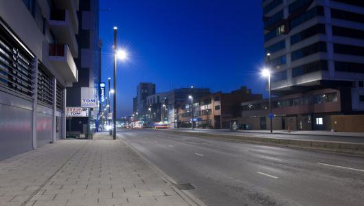
- Flooding. The essence of the method is to install and aim floodlights. It is used for illumination for security purposes in adjacent territories.
- General. This method involves evenly distributing lamps of the same type. It is ideal for lighting paths, parks, areas where people and cars move.
- Marking. With this type of street lighting, lamps are located along selected lines and shapes. It is used to create visual contours, emphasize relief, and highlight the direction of roads and pedestrian roads.
DESIGN OF ELECTRICAL LIGHTING FOR PRODUCTION PREMISES
For large and complex industrial complexes, buildings and structures, the lighting installation project is developed in two stages: technical design and working drawings.
In the technical project, issues of the lighting and electrical parts of the lighting installation are resolved, assignments are issued for the design of power supply and basic construction solutions.
Working drawings are developed on the basis of the approved technical design.
The development of a technical working draft or working drawings should be carried out in accordance with the environmental conditions in the premises; groups and categories of the environment and data on the power sources of the lighting installation must be established in full accordance with the PUE. When designing, it is recommended to study in detail the technological process of the illuminated enterprise and know the nature of the visual work performed in the premises.
The plans of the power supply network show the construction part of buildings in a simplified manner, display panels that indicate the number and installed power, and draw network lines indicating the brands and cross-sections of cables and wires. On the plans of the main premises, the installation locations of lamps and panels are fragmentarily outlined. Lamps, panels and various equipment are calculated according to plans and a table of indicators.
Drawings of plans and sections contain basic information about lighting solutions and the electrical part of lighting installations.
When developing plans, it is necessary to use a set of symbols and requirements for the implementation of inscriptions and numbers specified in GOST 21-614-88.
The plans include lamps, main points, group panels, step-down transformers, supply and group networks, switches, plug sockets; the names of the premises, the standardized illumination from general lighting, the class of fire and explosion hazardous premises, types, installation height of lamps and lamp power are indicated. , methods of wiring and cross-section of wires and cables of lighting networks (Fig. 2 a, b, c). The reference dimensions of installation locations for lamps, panels, and marks for laying lighting networks are indicated in cases where precise fixation of these locations is necessary.
When designing buildings, a number of rooms of which have the same lighting solutions: lamps, lighting network and other identical elements, it is recommended that all solutions be applied only for one room; for others, an appropriate reference is made to it. The general floor plan shows only the entrances to such premises. Drawings of floor plans of all premises are made on a scale of 1: 100 or 1: 200.
In addition to drawings of plans and sections of illuminated premises with lighting diagrams printed on them, the design documentation includes: custom specifications for electrical equipment and materials; construction buildings; remote control diagrams or other circuit diagrams, non-standard installation drawings.
Supply and group networks on floor plans are drawn with thicker lines than the building elements of the building and equipment; the number of wires in group lines is indicated by the number of notches drawn at an angle of 45 to the network line (Fig. 2)
Indication of groups throughout is necessary to ensure uniform phase loading. On panels without factory numbering of groups, connection phases are indicated. The plans include summary data, network voltages, links to symbols, grounding information.
Electric lighting is divided into working, emergency, evacuation (emergency lighting for evacuation), security. If necessary, some of the luminaires of one or another type of lighting can be used for emergency lighting (lighting during non-working hours). Artificial lighting is designed in two systems: general and combined, when local lighting (workplace lighting) is added to general lighting.
Working lighting should be installed in all areas of buildings, as well as in areas where work is being carried out and vehicles are moving.
The calculation of a lighting installation consists of two parts: lighting and electrical.
The lighting part contains: selection of light sources, standardized illumination, type and lighting system, type of lamps, safety factors and additional illumination; calculation of the placement of lamps (determining the height of the suspension, the distance from the walls and between lamps, the number of lamps), luminous flux and lamp power.
The electrical part of the project contains: selection of locations for main and group panels, network route and drawing up a power supply and lighting control circuit, type of wiring and method of laying it; calculation of the lighting network based on permissible voltage loss, followed by checking the cross-section for continuous current and mechanical strength, protection of the lighting network; recommendations for installing a lighting installation; measures to protect against electric shock.
Exercise № 2
Calculation of artificial lighting production premises
An important factor in ensuring comfortable working conditions is the creation of optimal lighting for production premises, workplaces, work areas outside buildings and the territory of the enterprise as a whole. For artificial lighting of industrial premises, mainly fluorescent lamps are used, and at a height of 12...14 m - mercury arc lamps. Due to their low efficiency, incandescent lamps are practically not used in modern enterprises.
The tasks of lighting calculations can be:
– determination of the lamp power required to provide a given illumination, with the selected type and location of lamps;
– determination of the number and location of luminaires of known power required to obtain a given illumination;
– determination of the expected (calculated) illumination with known type, location and power of lamps.
The most common method for calculating artificial lighting is the luminous flux utilization factor method:
where Ф is the required luminous flux of a mercury arc lamp (HAL) or a group of lamps of a fluorescent lamp, lm
E n – the required minimum standardized illumination in the room, lux, is selected according to SNiP 05/23/95 depending on the conditions and nature of visual work (Table 8).
S– area of the illuminated surface, i.e. room area, m2;
TO z – safety factor, taking into account the aging of the lamp and the dust content of the air in the room. Determined according to SNiP 23-05-95 (Table 9);
z– illumination unevenness coefficient, which is the ratio of the average illumination to the minimum illumination created by the lamp  . For DRL z = 1.15, for fluorescent lamps z = 1.1;
N– number of lamps, pcs;
η – coefficient of utilization of the luminous flux of the lamp (in fractions of a unit), selected according to reference data, based on the type of lamp, room index ( i) and reflection coefficients of the ceiling, walls and calculated surface table. 10, 11, 12).
Room index i determined by the formula:
 (25)
(25)
Where A And IN– length and width of the room, m;
N sv – distance from the luminaire to the design surface, m
 (26)
(26)
Where N– room height, m;
h n – distance from the ceiling to the lamp;
h p – distance from the floor to the calculated surface.
After determining the required luminous flux of the lamp, select the nearest standard lamp from the reference data (Tables 13, 14) and find the deviation of its luminous flux from the calculated one:
 ,
% (27)
Deviation within the range of -10% to +20% is allowed.
Completing of the work.
Design general uniform lighting of the physical and mechanical testing laboratory premises using OD type lamps with two fluorescent lamps. Room dimensions: length A = 20 m, width B = 8 m, height H = 3 m. Reflection coefficients of the ceiling ρ p 70%, walls ρ 50%, calculated surface ρ p 30%. Dust content in indoor air< 1 мг/м 3 .
1. According to SNiP 23-05-95 (Table 8) we determine E n depending on the nature of visual work:
E n = 200 lux.
2. Calculate the area of the illuminated surface, i.e. premises:
S=A*B=20*8=160m2.
3. We will find the lamp safety factor depending on the dust content in the room from the table. 9:
K z = 1.5 mg/m 3
4. Lighting unevenness coefficient for fluorescent lamps z = 1.1.
5. We set the number of lamps N and determine the layout of their hanging. We accept 14 lamps arranged in two rows.
The distance from the wall to the lamp is assumed to be  , Where l– distance between lamps, l= 2 m. Then
  m.
m.
6. Determine the room index using formula (25):
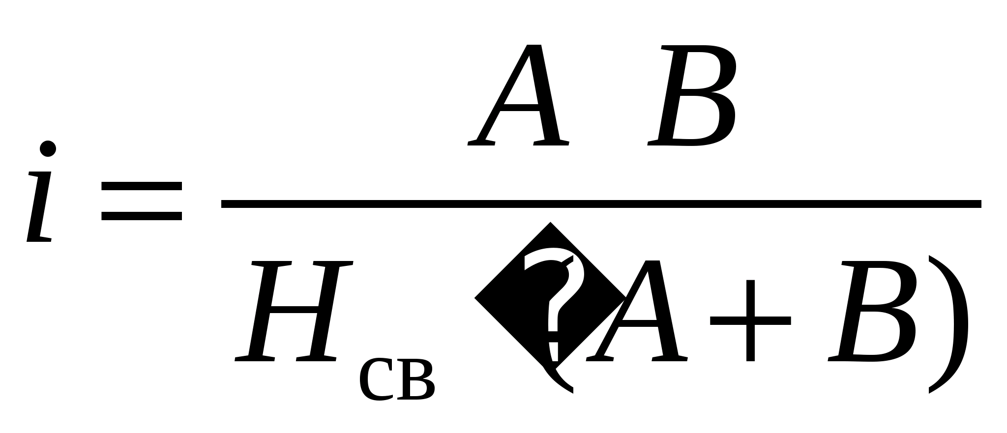
Given the fact that h n is 0.2 m, and h p we take 0.8 m, we determine:
H St =3-0.2-0.8=2m
Then =(20*8)/2*(20+8)=2.86
7. The coefficient of utilization of the luminous flux of an OD type lamp, taking into account the given reflection coefficients of the ceiling and walls, is determined according to Table 12. Accepted in fractions of a unit η = 0.55.
8. Then the required luminous flux is:
=(200*160*1.5*1.1)/(14*0.55)=6857lm
9. There are 2 lamps in the lamp, so the required luminous flux of one lamp is 6857:2=3428 lm. According to GOST 6825–74 (Table 14), we select the nearest standard fluorescent lamp LB 40 with a luminous flux of 3000 lm.
10. Let’s find the deviation of the luminous flux of the selected standard lamp from the one required by calculation:
 =(3428-3000)/3000*100=14,3,
which is within acceptable limits.
11. Thus, to illuminate the laboratory premises, 14 OD type lamps with two fluorescent lamps are required. The layout of the lamps is shown in the figure.

Lamp arrangement diagram
28. Industrial vibration: sources, physical characteristics, types of vibrations, effect on the human body, regulation, methods of protection
Vibration is a mechanical oscillatory movement directly transmitted to the human body from equipment and building structures on which it is installed.
Vibration occurs during the operation of machines and mechanisms that have unbalanced and unbalanced rotating organs or organs of reciprocating and impact motion. These include metalworking machines, forging and stamping hammers, electric and pneumatic hammer drills, power tools, as well as drives, fans, pumping units, compressors, etc.
Sources of vibrations in production are mobile construction machines, machines for vibration compaction of concrete mixtures, planing, grinding, hand-held mechanized tools, etc.
Vibration is characterized by:
Amplitude A, m;
Oscillatory speed υ, m/s;
Acceleration a, m/s2;
Oscillation period T, s;
Oscillation frequency f, Hz.
According to the method of transmission, vibration is divided into
General, transmitted through supporting surfaces to the body of a standing or sitting person;
Local, transmitted through hands.
The effect of vibration on a person depends on the direction of its action, therefore vibration is divided into those acting along the axes of the orthogonal coordinate system X, Y, Z.
General vibration, especially at frequencies of 5...25 Hz, close to human natural frequencies (6...9 Hz), has an adverse effect on the nervous, cardiovascular system, vestibular apparatus, and metabolism.
Local vibration, causing spasm of peripheral vessels, causes varying degrees of vascular, neuromuscular, and musculoskeletal disorders in the extremities (numbness, coldness, pain, musculoskeletal changes).
An occupational disease that develops under the influence of vibrations is called vibration disease. Vibration disease leads to disability (stages III, IV) and is difficult to treat. The effect of vibration is aggravated by low temperatures, which also caused spasm of blood vessels.
Table. The effect of vibration on the human body
Vibration oscillation amplitude, mm Vibration frequency, Hz Impact result
Up to 0.0 15 Various Does not affect the body
0.016–0.050 40–50 Nervous agitation with depression
0,051–0,100 40–50
Change in central nervous system, heart and hearing organs
0.101–0.300 50–150 Possible disease
0.101–0.300 150–250 Causes vibration disease
Vibration normalization is carried out in accordance with GOST 12.1.012–90 SSBT “Vibration. General safety requirements": according to the spectrum of root-mean-square vibrational velocity (m/s) (or acceleration, m/s2), its level (dB), as well as the vibration dose, taking into account frequency and time.
Local (local) (f = 8…1000 Hz), general vibrations are separately normalized; the latter are divided into transport (f = 1...63 Hz), transport-technological (f = 2...63 Hz) and technological (f = 2...63 Hz). To combat vibration at its source, it is necessary to focus on shockless equipment and technology, improve the quality of manufacturing and installation of mechanisms, improve the quality of road surfaces, etc.
In cases where it is not possible to reduce vibration at the source of its occurrence, it is necessary to use methods to reduce vibration along the propagation paths: vibration damping, vibration isolation or vibration damping.
The main indicator that determines the quality of any type of vibration protection is the vibration protection efficiency coefficient (transmission coefficient) µ, which is the ratio of the speed (acceleration) of the protected object after the vibration protection device (υ0, a0) to the value before the introduction of vibration protection (υ, a): µ = υ0 / υ = a0 / a, i.e. showing what proportion of the dynamic force excited by the machine F is transmitted to the base: µ = F0 / F.
Vibration damping is associated with the introduction of reactive resistance into the oscillatory system, which is achieved by increasing mass or rigidity. For this purpose, fans and pumps are installed on support plates and vibration-damping bases.
Vibration isolation is also achieved by installing equipment without foundations and anchoring units directly on elastic vibration-isolating supports. This reduces the cost of equipment installation and reduces the noise level associated with intense vibrations. Vibration insulation is provided when laying air ducts of ventilation systems inside building structures and when attaching them to them. To limit the spread of vibrations through air ducts, it is practiced to separate them into separate areas using flexible inserts.
Rubber or plastic gaskets, single or composite cylindrical springs, combined (spring-rubber) and pneumatic vibration isolators (“air cushions”) are used as vibration isolators.
Vibration damping. The basis this method It is planned to increase active losses in oscillatory systems by using vibration-damping coatings to reduce vibrations propagating through the air ducts of ventilation systems, as well as gas pipelines of compressor stations. The most common vibration-damping coatings include mastic (VD mastic, VPM, Antivibrit-M) and sheet (foam plastic, felt, vinyl pore, folgoizol) materials.
As preventive measures against vibration disease, a maximum duration of contact with a vibration source is established (no more than 2/3 of a shift, 20...30 minute breaks before and after lunch, 10...15 minute breaks every 50 minutes of work, continuous duration of exposure 15... 20 minutes), thermal procedures for the limbs, massage, gymnastics, mandatory periodic medical examinations.
The air temperature should be no lower than +16°C, humidity – 40...60%, air speed – 0.3 m/s.
For personal protection, safety shoes, protective gloves, and vibration-protective pads or plates are used.


