The hydraulic accumulator maintains the required pressure in the water supply and smoothes out interruptions in the operation of the pump.
If you have such a unit in your house, then you don’t need an archaic tank in the attic.
From the article you will learn how to connect a hydraulic accumulator to a well or borehole.
Using a hydraulic accumulator
How does a hydraulic accumulator work? The basis of the unit is a steel container separated by an elastic rubber membrane. One compartment contains air, the other is filled with water. The more water, the more the membrane stretches, reducing the space of the first chamber. The more the second chamber is filled, the higher the pressure in the first. Compressed air presses on the membrane, increasing water pressure. When the consumer uses water, the pressure decreases.
The upper and lower pressure limits are monitored by a sensor that sends a signal to the pump or control unit. When the water pressure in the system is below the set level (the sensor and controller are adjusted by selecting the required response limits), the pump relay turns on and water from the well enters the system. When the required pressure is reached, the pump turns off.
Pros and cons of using a hydraulic accumulator
The battery capacity, depending on the model, ranges from 5 to 100 liters. Therefore, the hydraulic accumulator, as a place for storing water, cannot stand any comparison with any tanks. The cost of a 100-liter hydraulic accumulator is 10-15 thousand rubles. The cost of a plastic tank with a capacity of 2-3 cubic meters 2-4 thousand rubles.
The hydraulic accumulator is used in conjunction with a deep or additional pump to create the pressure in the water supply necessary for operation household appliances. For example, washing machines and dishwashers, instantaneous water heaters(columns) do not work at pressures below 0.5-0.7 atmospheres (Bar).
Deep pumps and pumping stations supply water with a pressure of 3-5 atmospheres. Working with closed system, from which water is not taken, increases pump wear by 15-25 percent. Therefore, the water supplied by the pump is stored in a water tank or accumulator. The higher the tank is installed, the greater the pressure. Every meter of height increases water pressure by 0.1 atmosphere.
The larger the battery volume and the smaller the water withdrawal, the less often the automation turns on the pump. Switching on more than 6 times per minute increases pump wear by 20 percent. When turned on more than 10 times per minute, wear increases by 30-40 percent.
The use of a hydraulic accumulator extends the service life of the pump, reducing the frequency of switching on/
Connecting the hydraulic accumulator
Owners of private houses are interested in how to connect a hydraulic accumulator to a well. Next, you will learn what connection methods exist, and how to choose one or another method in different conditions.
Scheme "pump - check valve– hydraulic accumulator – pressure sensor.” This is the most simple circuit, which is used with submersible and semi-submersible pumps. The pump supplies water to the system to which the accumulator is connected. A pressure sensor is installed immediately behind the battery, which controls the pump.

How to choose a pump for such a system? If you consume more than 10 liters of water per minute, then use centrifugal pumps. They are 40-80 percent more productive, so they supply more water per minute than vibration ones. If the flow rate is less, use vibration pumps. If the water depth in a well or well is more than 3 meters, use only centrifugal pumps. The power of vibration pumps is not enough for the required water pressure.
If the water depth is more than 30 meters, use semi-submersible pumps.
Scheme: pump - check valve - tank - additional pump - hydraulic accumulator - pressure sensor.
This arrangement reduces the load on the main pump because it operates in a stable mode until the tank is filled. Turn the pump on and off manually or install a water level sensor in the tank to automatic control main pump. With this design, use submersible vibration pumps for the main and additional pumps. They are cheaper and have enough power to consume up to 20 liters per minute.
With more high flow rate use submersible centrifugal pumps for the main one, and surface centrifugal pumps for the additional one.

Use of pumping stations
The pumping station is a ready-made unit consisting of a surface centrifugal pump, a hydraulic accumulator with a capacity of 5-10 liters and a pressure sensor. If the water is more than 5 meters away, use the pumping station as an additional pump and pressure sensor, this is caused by the operating features of surface pumps.
Why does the station need an additional hydraulic accumulator?? The station pump, like other types of pumps, does not respond well to being turned on more than 5-6 times per minute. The capacity of the built-in HA is only sufficient to equalize pressure drops when turning the pump on and off. By connecting an additional GA, you will provide comfortable conditions pump operation and extend its service life.
Vertical or horizontal accumulator? The design of vertical and horizontal HAs is the same. Therefore, the one that best suits your conditions is better. If you have a lot of free space, use horizontal. If there is little free space, use a vertical one. The photographs show a horizontal aquasystem hydraulic accumulator and a vertical reflex accumulator with a volume of 200 liters.


Where to buy pumps, a station, a hydraulic accumulator and a pressure sensor? These devices are sold in hardware and construction stores. They can also be ordered through online stores.
When purchasing, do not forget to issue a warranty. Complex equipment breaks down from time to time, even with proper care.
Connecting the accumulator to deep well pump perform in compliance with safety regulations, turn off the electricity to avoid accidental activation of the pump. The pressure in the water supply is 1.5-2.5 atmospheres; by connecting a hydraulic accumulator or sensor, check all connections for leaks.
The use of a hydraulic accumulator extends the service life of pumps and increases the pressure in the water supply system. Correct Application the hydraulic accumulator turns plastic tank for water, two cheap vibration pumps and an inexpensive pressure sensor for a full-fledged pumping station. In terms of its performance, such a station is 2-3 times superior to industrial analogues of the same cost.
A correctly selected hydraulic accumulator connection diagram for water supply systems will ensure ease of operation, as well as durability and cost-effectiveness of the system. A hydraulic accumulator is an important component of the water supply system, which contains water and compressed air, separated by a membrane.
When the water flow parameters change (pressure decreases), the pump turns on and water is pumped into the accumulator, restoring the parameters of the required maximum pressure and then turns off. Further water flow comes from hydraulic device, preventing frequent switching on of the pumping unit, which occurs before next moment pressure drop to a minimum threshold. In addition, hydraulic accumulators can ensure the operation of the system for some time (depending on the volume of the tank) in the event of a power outage or damage to the pump.
IN general view All hydraulic accumulators consist of the following main parts:
- body with legs,
- membrane (in some models it is replaced by a rubber bulb located in the body according to the “vessel within a vessel” principle),
- air injection nipple, usually equipped with a protective cap.
Some products have distinctive design features:
- horizontal models are supplemented with a tap or valve for bleeding air,
- equipment for drinking water supplied with “pears” made from special grades of rubber, chemically neutral and not giving the liquid any foreign odors or tastes,
- hydraulic accumulators for heating systems are expansion tanks.
Based on the type of location, there are two types of models:
- Horizontal products are more often used for outdoor pumps. In such cases, pumping units are installed on hydraulic accumulators.
- Vertical models are often equipped with water supply systems with submersible pumps.
The choice of configuration and installation of a hydraulic accumulator for water supply systems at the same time can be carried out based on the availability of free space for the installation of a particular model.
According to their purpose, the following types of hydraulic accumulators are distinguished:
- for cold water supply (the most popular option, used not only in houses with permanent residence, but also at dachas),
- for hot water supply, made of materials capable of withstanding high temperatures and installed during the installation of a full-fledged system, including cold and hot water supply
Heating accumulators are painted red, and equipment for water supply systems (hot water supply and hot water supply) are painted blue.
Connecting a hydraulic accumulator to a submersible pump
Connection diagram of the hydraulic accumulator to submersible pump must include. Its presence will not allow compressed air to squeeze water back into the well through the membrane. The valve is mounted directly on the pump, before connecting other elements of the system.
 The photo shows a diagram of connecting a hydraulic accumulator to a submersible pump
 The first step is to install a submersible pump. To do this, use a rope and a weight to determine the depth of the well, after which a place on the rope is marked to which the pumping unit will need to be lowered so that it is at a distance of 20-30 cm from the bottom. After fixing the pump, its pressure pipe or hose that goes to the surface is connected to the pressure switch using a manifold (fitting) with five connectors. A hydraulic accumulator and a water supply system are connected in series to the same collector for supply to points of consumption. The remaining connector is used to connect the equipment control system.

Connecting a submersible pump to a hydraulic accumulator, like the other systems described below, necessarily requires sealing of all connections. For this purpose it is used FUM tape or tow with sealant.
Connection to surface pump
Before you begin connecting the hydraulic accumulator to the surface pump, you need to determine the required water supply parameters, in particular, decide what pressure is needed in the system. It is believed that water supply with a small number of consumption points can operate at a pressure of 1.5 atm. Depending on the availability of equipment that requires high pressure, this value can increase to 6 atm., more high blood pressure considered dangerous for communications and connecting elements.
Considering the selected pressure to be nominal, it is determined what reduction should be considered acceptable, that is, At what value will the pump turn on?. Critical value set on the control relay, and from the nipple side the air pressure in the accumulator is measured in the absence of water in it. The resulting value should be 0.5-1.0 atm below the minimum acceptable value.
 The connection diagram of the hydraulic accumulator to the surface pump is the same as when connecting a pumping station, the package of which already includes a hydraulic accumulator
 If no adjustment is required in this direction (for example, pumping), a hydraulic accumulator connection diagram for water supply systems is assembled
using a five-input collector. The hydraulic accumulator is installed first, then sequentially: pressure pipe pump, domestic water supply, pressure switch, pressure gauge.
Connecting the pumping station
To prevent the pump from turning on every time the tap is opened, a hydraulic accumulator is installed in the system. It contains a certain volume of water, sufficient for a small flow rate. This allows you to practically get rid of short-term pump starts. Installing a hydraulic accumulator is a simple procedure, but you will need a few more devices - at a minimum - a pressure switch, and it is also desirable to have a pressure gauge and an air vent.
Functions, purpose, types
Installation location - in a pit or in a house
In the water supply system of a private house without a hydraulic accumulator, the pump turns on whenever water flows somewhere. These frequent starts lead to wear and tear on the equipment. And not only the pump, but the entire system as a whole. After all, every time there is an abrupt increase in pressure, and this is a water hammer. To reduce the number of pump starts and smooth out water hammer, a hydraulic accumulator is used. The same device is called expansion or membrane tank, hydraulic tank
Purpose
We found out that one of the functions of hydraulic accumulators is to smooth out water hammer. But there are others:

It is not surprising that most private water supply systems have this device - there are many advantages from its use.
Species
A hydraulic accumulator is a tank made of sheet metal divided into two parts by an elastic membrane. There are two types of membrane - diaphragm and balloon (bulb). The diaphragm is attached across the tank, a pear-shaped cylinder is secured at the inlet around the inlet pipe.
According to their purpose, they are of three types:
- for cold water;
- for hot water;
- for heating systems.
Hydraulic tanks for heating are painted red, tanks for water supply are painted blue. Expansion tanks for heating are usually smaller in size and more low price. This is due to the membrane material - for water supply it must be neutral, because the water in the pipeline is potable.

Depending on the type of arrangement, hydraulic accumulators can be horizontal or vertical. Vertical ones are equipped with legs; some models have plates for hanging on the wall. It is the models elongated upward that are most often used for self-creation water supply systems of a private house - they occupy less space. The connection of a hydraulic accumulator of this type is standard - through a 1-inch outlet.
Horizontal models are usually equipped with pumping stations with surface-type pumps. Then the pump is placed on top of the container. It turns out compact.
Operating principle
Radial membranes (in the form of a plate) are used mainly in gyroaccumulators for heating systems. For water supply, a rubber bulb is usually installed inside. How does such a system work? As long as there is only air inside, the pressure inside is standard - the one that was set at the factory (1.5 atm) or that you set yourself. The pump turns on, begins to pump water into the tank, and the pear begins to increase in size. Water gradually fills an increasingly larger volume, increasingly compressing the air that is located between the wall of the tank and the membrane. When a certain pressure is reached (usually for one-story houses this is 2.8 - 3 atm) the pump is turned off, the pressure in the system stabilizes. When you open a tap or other water flow, it comes from the accumulator. It flows until the pressure in the tank drops below a certain level (usually about 1.6-1.8 atm). After which the pump turns on, the cycle repeats again.

If the flow rate is large and constant - you are filling a bathtub, for example - the pump pumps water in transit, without pumping it into the tank. The tank begins to fill after all the taps are closed.
A water pressure switch is responsible for turning the pump on and off at a certain pressure. In most hydraulic accumulator piping schemes, this device is present - such a system operates in optimal mode. We’ll look at connecting the hydraulic accumulator a little lower, but for now let’s talk about the tank itself and its parameters.
Large tanks
Internal structure hydraulic accumulators with a volume of 100 liters and above are slightly different. The pear is different - it is attached to the body both at the top and at the bottom. With this structure, it becomes possible to fight the air that is present in the water. To do this, there is an outlet in the upper part into which you can connect a valve for automatic air release.

How to choose tank volume
You can choose the tank volume arbitrarily. There are no requirements or restrictions. The larger the volume of the tank, the greater the supply of water you will have in case of a shutdown and the less often the pump will turn on.
When choosing a volume, it is worth remembering that the volume that appears in the passport is the size of the entire container. There will be almost half as much water in it. The second thing to keep in mind is overall dimensions containers. A 100 liter tank is a decent-sized barrel - about 850 mm high and 450 mm in diameter. You will need to find a place somewhere for it and the harness. Somewhere - this is in the room where the pipe from the pump comes. This is where all the equipment is usually installed.

If you need at least some guidelines to choose the volume of the hydraulic accumulator, count average consumption from each water intake point (there are special tables or can be found in the passport for household appliances). Sum up all this data. Get possible consumption in the event that all consumers work simultaneously. Then figure out how many and which devices can work at the same time, calculate how much water will be consumed in a minute in this case. Most likely by this time you will have already come to some decision.
To make it a little easier, let’s say that the hydraulic tank volume of 25 liters is enough to meet the needs of two people. It will ensure the normal functioning of a very small system: a faucet, a sink and a small one. If there is another household appliances the capacity needs to be increased. The good news is that if you decide that the current tank is not enough for you, you can always install an additional one.
What should be the pressure in the accumulator?
One part of the accumulator contains compressed air, and water is pumped into the second. The air in the tank is under pressure - factory settings - 1.5 atm. This pressure does not depend on the volume - it is the same on a tank with a capacity of 24 liters and 150 liters. The maximum permissible maximum pressure may be more or less, but it does not depend on the volume, but on the membrane and is indicated in the technical specifications.

Preliminary check and pressure correction
Before connecting the accumulator to the system, it is advisable to check the pressure in it. The settings of the pressure switch depend on this indicator, and during transportation and storage the pressure could drop, so monitoring is very desirable. You can control the pressure in the hydraulic tank using a pressure gauge connected to a special input in the upper part of the tank (capacity of 100 liters or more) or installed in its lower part as one of the piping parts. Temporarily, for control, you can connect a car pressure gauge. Its error is usually small and it is convenient to work with. If this is not the case, you can use the standard one for water pipes, but they are usually not very accurate.

If necessary, the pressure in the accumulator can be increased or decreased. There is a nipple at the top of the tank for this purpose. A car or bicycle pump is connected through the nipple and the pressure is increased if necessary. If it needs to be vented, the nipple valve is bent with some thin object, releasing the air.
What air pressure should be
So should the pressure in the accumulator be the same? For normal operation household appliances require a pressure of 1.4-2.8 atm. To prevent the tank membrane from tearing, the pressure in the system should be slightly more pressure tank - by 0.1-0.2 atm. If the pressure in the tank is 1.5 atm, then the pressure in the system should not be lower than 1.6 atm. This value is set on the water pressure switch, which works in tandem with the hydraulic accumulator. These are the optimal settings for a small one-story house.
If the house is two-story, you will have to increase the pressure. There is a formula for calculating the pressure in the hydraulic tank:
Vatm.=(Hmax+6)/10
Where Hmax is the height of the highest point of water intake. Most often this is a shower. You measure (calculate) at what height relative to the hydraulic accumulator its watering can is located, substitute it into the formula, and get the pressure that should be in the tank.

If the house has a jacuzzi, everything is more complicated. You will have to select it empirically - changing the relay settings and observing the operation of water points and household appliances. But at the same time, the operating pressure should not be greater than the maximum permissible for other household appliances and plumbing fixtures (indicated in the technical specifications).
How to choose
The main working body of the hydraulic tank is the membrane. Its service life depends on the quality of the material. The best membranes today are made from food-grade rubber (vulcanized rubber plates). The housing material matters only in membrane-type tanks. In those in which a “pear” is installed, water comes into contact only with rubber and the material of the body does not matter.

The flange should be made of thick galvanized steel, but better - stainless steel
What's really important about bulb tanks is the flange. It is usually made of galvanized metal. In this case, the thickness of the metal is important. If it is only 1 mm, after about a year and a half of operation, a hole will appear in the metal of the flange, the tank will lose its tightness and the system will stop working. Moreover, the warranty is only one year, although the stated service life is 10-15 years. The flange usually rots after completion warranty period. There is no way to weld it - the metal is very thin. You have to search in service centers new flange or buy a new tank.
So, if you want the accumulator to last a long time, look for a flange made of thick galvanized or thin, but made of stainless steel.
Connecting the accumulator to the system
Typically, the water supply system of a private home consists of:

This scheme may also contain a pressure gauge for operational pressure control, but this device is not necessary. It can be connected periodically to carry out test measurements.
With or without five-pin fitting
If the pump is of a surface type, the hydraulic accumulator is usually placed next to it. In this case, the check valve is installed on the suction pipeline, and all other devices are installed in one bundle. They are usually connected using a five-pin fitting.

It has conclusions with different diameters, just for the devices used for tying the hydraulic accumulator. Therefore, the system is most often assembled on its basis. But this element is completely optional and everything can be connected using ordinary fittings and pieces of pipe, but this is a more labor-intensive task, and there will be more connections.

How to connect a hydraulic accumulator to a well - diagram without a five-pin fitting
With one inch outlet, the fitting is screwed onto the tank - the pipe is located at the bottom. A pressure switch and pressure gauge are connected to the 1/4 inch outlets. The remaining free inch terminals are connected to the pipe from the pump and wiring to consumers. That's all for connecting the gyroaccumulator to the pump. If you are assembling a water supply diagram with surface pump, you can use a flexible hose in a metal winding (with inch fittings) - it’s easier to work with.

A visual diagram of connecting the pump and accumulator - use hoses or pipes where necessary
As usual, there are several options, the choice is yours.
The hydraulic accumulator is connected to the submersible pump in the same way. The whole difference is where the pump is installed and where the power is supplied, but this has nothing to do with the installation of the accumulator. It is placed in the place where the pipes from the pump enter. Connection is one to one (see diagram).

How to install two hydraulic tanks on one pump
When operating the system, sometimes owners come to the conclusion that the available volume of the accumulator is not enough for them. In this case, you can install a second (third, fourth, etc.) hydraulic tank of any volume in parallel.

There is no need to reconfigure the system; the relay will monitor the pressure in the tank on which it is installed, and the viability of such a system is much higher. After all, if the first accumulator is damaged, the second one will work. There is another positive point - two tanks of 50 liters each cost less than one of 100. The point is that the technology for producing large-sized containers is more complex. So it is also more economical.
How to connect a second accumulator to the system? Screw a tee onto the input of the first one, connect the input from the pump (five-pin fitting) to one free output, and connect the second container to the remaining free one. All. You can test the circuit.
Today it’s hard to even imagine country house without water supply system. However, in addition to pumping equipment for a well or well, in some cases it may be necessary to install a hydraulic accumulator. This device is used if, after lifting from the well, water cannot be delivered to all water collection points. The hydraulic accumulator helps regulate water pressure in the water supply system. There are different schemes for connecting the hydraulic tank to the water supply network. The choice of one scheme or another depends on the pump used. In our article we will look at a diagram for connecting a hydraulic accumulator to a submersible pump installed in a well or well.
A hydraulic accumulator is a cylindrical metal container with a rubber bulb inside it. This pear functions as a membrane. In essence, a hydraulic tank is a link in the water supply system. It is capable of accumulating a certain volume of liquid and creating the necessary water pressure in the pipeline. Due to the fact that the required pressure is created in the system, it is ensured efficient work sanitary appliances, washing and dishwasher, as well as supplying liquid to the upper floors of a residential building and to the most remote points.
The hydraulic accumulator itself consists of the following components:
- membrane in the form of a rubber bulb- This is an elastic product that is attached to the inlet part of the tank and is located inside the body. A flow flange with a valve is installed in the neck of the container;
- metal body with legs– this is a sealed tank that can cope with operating pressure from 1.5 to 6, and sometimes 10, atmospheres;
- nipple with safety closing mechanism located with reverse side housings. This device allows you to pump air into the space between the rubber bulb and the walls of the housing.
In addition, for the operation of the entire water supply system with a hydraulic tank, a pressure switch is required, which allows you to maintain a given pressure in the system and controls the start and stop of the submersible pump, as well as a check valve.
A special flange is used to fix the rubber bulb to the body. Its design has an inlet pipe. The internal structure of this tank is designed so that there is air between the membrane and the walls of the housing. It must be under a certain pressure, which is pumped into the chamber using a car or bicycle pump. This air not only helps maintain the required pressure in the water supply system, but also counteracts overextension of the bulb into which water is pumped using a submersible pump from a well or well.
All hydraulic accumulators can be divided into several types:
- units designed to work with cold water supply systems;
- devices for hot water pipelines;
- hydraulic expansion tanks for heating systems.
In our article we will look at the connection diagram and operating principle of a hydraulic tank for cold water supply systems. This tank is designed in such a way as to accumulate the required volumes of water and ensure the supply of liquid to the water distribution points. Such equipment allows you to avoid water hammer and protect borehole pump from frequent switching on.
Operating principle

The operation diagram of the hydraulic tank after connecting it to the water supply system is as follows:
- Using a submersible pump, water is pumped from a well or well into the rubber bulb of the tank.
- As water is pumped in, the air pressure in the chamber between the walls of the housing and the rubber bulb increases due to the stretching of the membrane by water. When it reaches the maximum set on the relay, the contacts open and the pump turns off.
- At the same time, you can continue to use water due to the fact that the membrane pushes it to the point with an open tap, household appliances or sanitary fixture. As the volume of liquid in the rubber bulb decreases, its walls put less pressure on the air in the chamber and the pressure gradually decreases. When it reaches the minimum set on the relay, the contacts close and the pump starts working again and pumping water from the well or well into the tank.
- Then the cycle repeats.
Important: the frequency of starting well pumping equipment is directly related to the volume of the rubber bulb and the intensity of water consumption. That is, the volume of the tank must be selected taking into account the water needs of a particular family, so that the frequency of startup of the pumping unit does not increase, and this does not lead to its rapid wear.
Advantages of using a hydraulic tank

- Thanks to the large capacity of the tank, you always have a supply of water, even if the water in the source disappears for some reason.
- Using this equipment, you can maintain the required pressure in the water supply system, which will provide you with a uniform supply of liquid at all water distribution points.
- The hydraulic tank reliably protects the system from water hammer.
- The service life of pumping equipment is increased due to less frequent unit starts.
- By injecting water into the pipeline, optimal conditions for operation of household appliances (washing machine and dishwasher).
Installation Features

- well pump;
- relay;
- pipeline for supplying water from pumping equipment to the tank and from it to water collection points;
- check valve;
- shut-off valves;
- filter device for rough water purification;
- drainage into the sewer system.
The connection diagram to a surface pump or pumping station looks much simpler, since it is carried out block installation relay, that is, it is installed in conjunction with pumping equipment; there is also a built-in coarse filter and check valve.
Connecting the hydraulic accumulator

When connecting a hydraulic tank to submersible pumping equipment, a check valve must be used, which prevents water from flowing back into the supply pipeline and source after the pumping equipment is turned off. Otherwise, after turning off the pump, the air from the tank will squeeze water into the well.
The check valve is mounted on pumping equipment before connecting all other elements of the water supply system. Further work proceed in the following sequence:
- First you need to properly install the submersible pump. To do this, you need to use a rope with a load to measure the depth of the well or well. After this, the wet spot on the rope can be used to determine the immersion depth of the pumping equipment.
Important: the well pump should be lowered below the water surface no more than 30 cm.
- After the pump is lowered into the well, the cable on which it is attached is securely fixed to the surface at the head of the hydraulic structure.
- After this, the hose or pipeline coming from the pumping unit on the surface is attached to the relay using a special fitting. This fitting must have five connectors.
- After this, you need to connect the water supply system going into the house and the hydraulic tank to the connectors on the fitting. Also, a control device for the entire water supply system must be connected to another connector.
Attention: all connections must be carefully sealed using tow treated with sealant or FUM tape.
- Now you can configure the relay.
Relay settings

For effective and proper operation hydraulic tank and the entire water supply system, the relay must be configured correctly. Since this unit usually comes with factory settings, this is done in the following sequence:
- If there is water in the system, it must be drained by opening the bottom tap.
- Now you can open the cover on the relay and turn on the pump to pump water.
- At the moment the pumping equipment is turned off, you need to take the pressure gauge readings and write them down.
- After this, open the most remote tap in the system and wait for the pumping equipment to start again after a certain amount of water has flowed out. At this moment, record the pressure gauge readings and write them down. Now we find the difference by subtracting from more smaller value. It should be equal to 1.4 bar. If your indicator is lower, you need to tighten the nut installed on the small spring. If the found number is greater, this nut must be loosened.
- Moreover, if at the moment the water flows out of the most remote tap, you do not like the pressure, then you need to tighten the nut on the large spring after disconnecting the unit from the network. To make the pressure less, you need to loosen the nut on the contrary.
- After the setup is completed, the system is launched and its effectiveness is checked. The setting can be repeated several times until you are completely satisfied with how the water supply system works.
Most of the work related to the development and installation of water supply systems requires some experience and a clear understanding of the specifics of the operation of a water supply system based on an artesian well. But even in this not an easy task There are many individual elements and assemblies that you can easily install with your own hands. For example, connect a hydraulic accumulator and a pressure switch to the pump. The complexity of such work is minimal; installing a hydraulic accumulator for water supply systems does not require special skills or knowledge of electrical installation; you will need the attitude to conscientiously carry out the installation yourself and a competent water supply scheme.
What and how needs to be adjusted in a system with a pump and accumulator
There are three classic version layout of pumping and accumulator equipment for a well:
- In the first case, a submersible pump is used, located in the well under a layer of water of 1-2 meters; the automation, filter and hydraulic accumulator can be located in a caisson at the well head, but with the same success, installation for all equipment can be done in basement Houses;
- In the second case, a surface pumping system and a hydraulic accumulator are used, which does not have the pressure capabilities of submersible units, so they try to locate them as close as possible to the well and the water level. Most often, a pump with a water pressure switch and the hydraulic accumulator itself are mounted in the caisson;
- In the third option, also called the dacha and garden option, water from the well is lifted by a surface pump unit or a simple vibrating “Baby” in a huge water tank. Water can be supplied to the home water supply without using additional pumping device, only natural pressure of the water column, water the beds and refill summer shower, wash equipment, in general, use the installation at your own discretion.
For your information! In any case, before setting up the accumulator pressure switch, you will need to correctly calculate the required water pressure in the house, taking into account the requirements of household appliances and the existing height difference between the pump level and the maximum water withdrawal point in the house, most often this is the air release valve of the heating system.
Sequence of work when installing a hydraulic accumulator with your own hands
Immediately after drilling the well and determining the flow rate, they begin its arrangement. Based on the depth of the aquifer and the degree of its contamination with salts and sand, a decision is made on the method of designing the head, where it is necessary to install the pump, and which option pumping system and pumped storage installation fits better everything.
Installation of a hydraulic accumulator paired with a submersible pump
A submersible pumping unit has always had a lot of advantages, but the more powerful and advanced the pump, the larger the volume of the pumped storage unit must be used to compensate for pulsation and water hammer. Therefore, when choosing an installation scheme for pumping equipment and a hydraulic accumulator device, the system parameters were sequentially determined:
- Required pressure and water flow to ensure normal water supply to the house, taking into account the depth of the well and the distance from the head of the house;
- What pump power and hydraulic accumulator tank volume will provide the necessary performance and smooth operation of water supply systems;
- Where to locate the main components of the water supply system equipment: pump, hydraulic accumulator, automation and filters.
For your information! To ensure the operation of expensive and powerful pumping systems from Danish, German and Italian manufacturers, they most often use hydraulic accumulators from 50 to 100 liters, which are installed in a designated area of the basement or ground floor.

The high pressure and pressure of “European” models make it possible to install pumped storage units at a considerable distance from the well, even if the building has a second floor and household appliances that require increased water pressure in the water supply system.
Standard piping connections are shown in the diagram.
This option of installing a hydraulic accumulator in a water supply system provides a number of significant advantages:
- A well-ventilated and partially heated room allows you to prevent condensation on the surface of the hydraulic accumulator and electrical automation systems;
- It is convenient to maintain the hydraulic accumulator tank and filter, according to existing standards It is recommended to check the pressure gauge readings air chamber battery cylinder and setting the pressure switch for the hydraulic accumulator at least once every two to three months;
- If necessary, you can drain water from the water supply system directly into a reserve tank or into the sewer system.
Important! Installation of a pumped storage device in a separate room requires that polypropylene pipes be laid in the ground to a depth of at least the freezing depth with a slope towards the well of at least 2°. This will ensure that air bubbles escape to the filter and the connection point of the hydraulic storage tank.
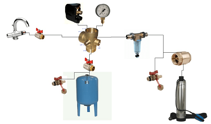
The basis for constructing such a water supply system unit is a hydraulic accumulator tank, most often vertical on supports. A five-pin fitting is screwed into the bottom of the tank, through which the pump line, outlet line, pressure switch sensor and pressure gauge are connected. The pump line from the well to the accumulator is most often made of polypropylene pipe. In small water supply systems, connections can be made with flexible hoses, and the relay and filter are usually located on a special mount at a height of at least a meter above the floor.

The disadvantages of such schemes include the sensitivity of submersible pumping systems to a high content of sand and salts. Check valve in submersible systems most often located at the outlet of the pump at great depth. After a certain amount of water rises, the sand remaining in the outlet pipe slowly settles, sinking to a depth, and gradually accumulates on the body of the check valve and gets inside the device, which leads to failure of the expensive unit.

For domestic submersible pumps of the “Vodomet” type, installation can be carried out in a caisson or head well. Most often, this scheme is used for low-power pumping systems, with a shallow aquifer.
In the photo you can see the classic correct option installation of a submersible pumping system and a hydraulic accumulator in a well.
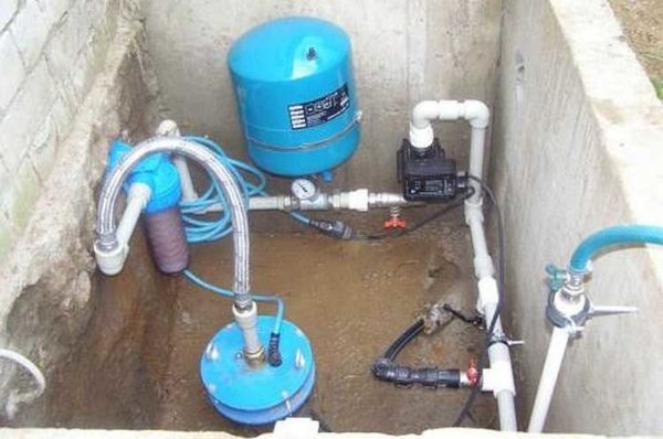
The output from the well neck is supplied to the filter, then to the hydraulic accumulator, and only after that to the pressure switch of the submersible pump. Output from the well to the filter and hydraulic accumulator is completed flexible hose, all other fittings are soldered from plastic pipes. What does such a scheme provide? This installation allows you to supply sand-free water to the hydraulic accumulator and relay.
By connecting the system to the water main through a filter, the reliability of the automation is significantly increased. The relay must be as free from dirt and sand as possible, otherwise after a couple of months there will be interruptions in operation.
In the central part of the outlet line running from the pressure switch to the entrance to the water supply system of the house, there is ball valve with a tee, which allows you to solve a rather difficult question: how to drain water when adjusting the response pressure of the automatic relay.
For large differences in height, or if the water in the well is of very low quality, install additional pumped storage devices with volume separation clean water and technical water. The system consists of two hydraulic accumulators and a clean water tank. Included with the pump in the well, a hydraulic accumulator-storage unit for untreated water is standardly installed, from which the liquid, through a filter of dirt and neutralization of suspended matter, enters the inlet of a vortex pump, which pumps water through membrane filters into a hydraulic accumulator for clean water, located in the house or basement. Water is taken from the tank and sent to the point of use in the water supply system by a conventional network pump.
The pumping device that takes untreated water from the well must be as insensitive as possible to the content of hard salts and clay suspension in artesian water.
Easy installation of a hydraulic accumulator with a surface pump
It is best for these purposes to install a properly configured centrifugal pump with an ejector and a small accumulator. The first hydraulic accumulator will not be used as a backup source of water, so you can limit yourself to a small membrane model of 10-12 liters.
There are no particular differences in the use and installation of a hydraulic accumulator with a surface pump, except that:
- The installation of the hydraulic accumulator and pressure switch should be carried out as close as possible to the pump;
- Between centrifugal pump and the hydraulic accumulator must have a filter and a check valve, otherwise every time you turn it on water tap with noise and vibration you will get a mixture of air and water.
Country and garden option for installing a hydraulic accumulator
The dacha and garden option, for all its primitiveness, allows you to very rationally use the capabilities of pumps with high water flow and get by without minimum size hydraulic accumulator.
The advantages of the pump installation option shown in the photo are obvious. Firstly, there is no need to install a large and expensive hydraulic accumulator, which does not always make sense to purchase for the needs of a summer house. Secondly, the relay on the pump can be connected with a flexible hose to the point where water is taken from the tank and adjusted to a minimum of 0.1 and 0.2 atm off and on, respectively. In some cases, the pressure switch-membrane is replaced with an electromechanical timer, which allows a certain volume of water to be pumped out of a well or borehole at a programmed period of time.
Conclusion
All of the above options for installing a hydraulic accumulator have been tested in practice and have proven their reliability. If the water quality in your estate or private home leaves much to be desired, use the pump method given in the article with two hydraulic accumulators and a membrane filter for water purification. Most branded hydraulic accumulators have a certified rubber shell, in which you can store a supply of purified drinking water for a long time. For technical needs, you can use a regular tank, described in the last subsection, complete with a small and cheap vortex pump.